Automated Packaging Box Tape Dispenser With Length Precision Encoding Via Arduino
Labels like "FRAGILE DO NOT DROP” are a great way to advise people on what to do (or not to do) with a box or other sensitive item. However, separating the sticker from its backing isn’t always easy, an effect that would certainly be exacerbated after doing this over and over... and over. To help alleviate this potential de-backing issue, Mr Innovative has come up with an automated machine with Arduino .
This device is constructed mostly out of wood using hand tools, along with a variety of 3D-printed and off-the-shelf parts. It features a NEMA 17 motor to pull the rolled-up labels over a series of rods, and during this process, the front of one label separates from the backing sheet after a particularly sharp turn. The label is then easily removed, and another label soon takes its place.
Control of the label separator is via an Arduino Nano on a custom PCB, with an A4988 driver employed to interface with the stepper directly. A 16x2 I2C LCD display gives user feedback, while a rotary encoder input dictates the length of each label. An infrared sensor detects the presence of the half-hanging sticker, and when it’s removed and the roll needs to be advanced. The build also tracks the number of labels that are used, which could be especially handy in some situations. Code for the project can be found on GitHub .
This project is great learning for 3D printing, Mechanics, electronics and programming
Label dispensing is a critical point in many industries like, E-comerce, FMCG, automobile and many more.
if you have small or large business you definitely preparing parcel of you final goods to dispatched.
for that parcel, you definitely need a label sticker to paste on the parcel. it may be a warning, invoice, receipt, or thanks for shopping wish.
Imagine you have hundreds of parcel to dispatch and manually pealing label one by one is very tough job to do.
So here my this auto label dispenser machine can help you to dispense label for you. and make our dispatch prosses fast
These components are integral to your electronics DIY project, serving various functions such as control, motion, structural support, and sensing, depending on the project's specific requirements.
Making the frame for a label sticker dispenser machine is like building the skeleton of a robot. This frame will hold everything together and make sure the machine works smoothly. We'll use some materials like a 20x20 aluminum frame, a Nema 17 stepper motor, an 8mm smooth rod, 8mm pillow bearings, and some 3D printed parts.
Gather all the materials you need. These include the aluminum frame, the Nema 17 stepper motor, the 8mm smooth rod, 8mm pillow bearings, and 3D printed parts. Make sure everything is clean and in good condition.
Lay out the 20x20 aluminum frame pieces on a flat surface to create the base of the machine. Make sure they fit together properly. You might need to use screws or brackets to secure them in place. This base will provide stability for your machine.
Now, fix the Nema 17 stepper motor to the frame. It's like attaching the heart of the machine. This motor will help the machine move the stickers.
Slide the 8mm smooth rod into the pillow bearings. These bearings will make sure the rods can turn smoothly. Attach these rod and bearing assemblies to the frame. Think of them as the machine's arms that will carry the stickers.
You might have some 3D printed parts that are custom-made for your machine. Attach these parts to the frame as needed. They can be like the hands and fingers of the machine, helping with the sticker dispensing process.
In the assembly of your label sticker dispenser machine, it's important to have clear and accurate wiring connections to ensure proper functionality. Here's a detailed write-up on how the wiring is set up for your project:
By following these wiring connections, you ensure that your label sticker dispenser machine is set up to control the stepper motor accurately, receive input from the IR sensor, and run on the appropriate power supply. This organized and well-connected system is crucial for the successful operation of your project.
We're excited to introduce our latest project, made possible with JLCPCB's exceptional PCB service. We ordered our PCBs from JLCPCB , and the results have been outstanding.
Our multipurpose PCB is a game-changer, designed to serve a multitude of projects. With JLCPCB's top-quality boards, you can now rely on a single PCB for a wide range of applications. Say goodbye to the hassle of designing new PCBs for every project.
JLCPCB is our trusted partner because they offer the best in PCB quality without breaking the bank. The precision and reliability of their boards are unparalleled, making our projects run seamlessly every time.
No matter your project - be it electronics, automation, or innovation - our multipurpose PCB, crafted with JLCPCB's expertise, will be your go-to solution. It's the smart choice for streamlining your work and reducing costs.
Join the league of innovators who rely on JLCPCB for the best quality PCBs at incredibly affordable rates. Get ready to take your projects to new heights with JLCPCB as your trusted PCB partner.
JLCPCB 1-20 Layer PCB from $2, Sign up to Get $54 Coupons here: https://jlcpcb.com/?from=MrI
// Motor steps per revolution. Most steppers are 200 steps or 1.8 degrees/step #define MOTOR_STEPS 200 #define RPM 120 int flag = 0;
// Since microstepping is set externally, make sure this matches the selected mode // If it doesn't, the motor will move at a different RPM than chosen // 1=full step, 2=half step etc. #define MICROSTEPS 16
// All the wires needed for full functionality #define DIR A0 #define STEP A1 //Uncomment line to use enable/disable functionality //#define SLEEP 13
// 2-wire basic config, microstepping is hardwired on the driver BasicStepperDriver stepper(MOTOR_STEPS, DIR, STEP);
//Uncomment line to use enable/disable functionality //BasicStepperDriver stepper(MOTOR_STEPS, DIR, STEP, SLEEP);
void setup { stepper.begin(RPM, MICROSTEPS); // if using enable/disable on ENABLE pin (active LOW) instead of SLEEP uncomment next line // stepper.setEnableActiveState(LOW); pinMode(4,INPUT); Serial.begin(9600); }
The code includes the necessary libraries for Arduino and the "BasicStepperDriver" library for controlling the stepper motor.
Here, constants are defined for the number of motor steps per revolution (200) and the desired revolutions per minute (RPM). The variable flag is also initialized to 0.
This constant defines the number of microsteps per full step. In this case, it's set to 16, which means the motor will perform 16 microsteps for each full step, providing smoother and more precise motion.
Here, the digital pins used for controlling the stepper motor are defined. DIR is the direction pin (A0), and STEP is the step pin (A1). There is also a line of code that can be uncommented to define an additional pin for enabling/disabling the motor, but it is currently commented out in this code.
An instance of the BasicStepperDriver class is created, specifying the number of motor steps, the direction pin, and the step pin. This class simplifies the control of the stepper motor.
This code appears to control a stepper motor based on input from an IR sensor, stopping and starting the motor's rotation depending on the sensor's state and the flag variable.
Masking tape makes for a great label as its weak adhesive does not tend to leave visible residue and names can be easily sketched onto its surface, albeit quite slowly. To expedite this process, Hackaday.io user michimartini decided to design and build a machine that writes labels automatically .
The device is essentially a drum plotter, which rotates a cylinder around an axis while moving the writing head back and forth to draw. For the X axis, michi used a basic NEMA17 stepper motor in conjunction with a CNC shield connected to an Arduino Nano . And rather than creating a custom horizontal Y axis from scratch, the machine instead utilizes a repurposed linear assembly extracted from an old DVD drive carriage, while a limit switch assists in homing the toolhead. Finally, a small servo motor holds the writing utensil so that it adequately contacts the masking tape.
To actually print a label, the text is first entered into a specialized program running on an old Odroid-C1 single-board computer, which converts the string to a G-code path that the Grbl-based firmware can understand. After the user has verified everything looks good on the attached 3.2″ LCD screen, the Nano begins to plot the characters.
Hardware Schematics & Pinout Diagrams
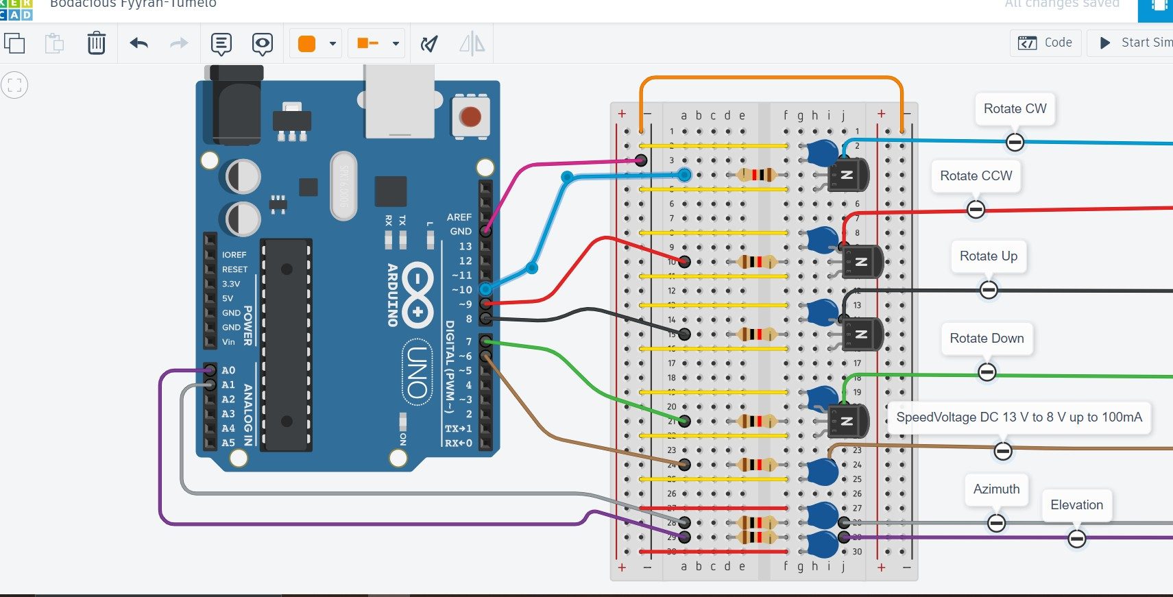
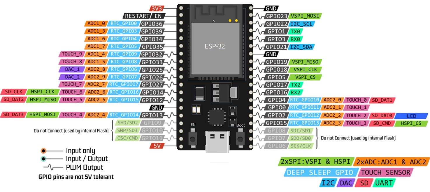
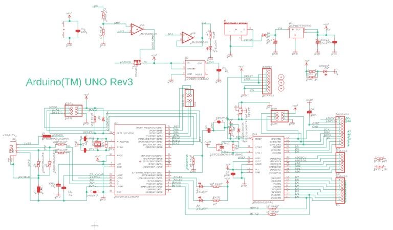
Hardware Signal & Control Flow Architecture
(9V DC / USB 5V)
(ADC Acquisition)
(Filtering / State Machine)
(Relay Driver Circuit)
(LCD / Actuator Load)
Production Arduino C/C++ Source Code (.ino)
[*] Initializing Hardware Core for Automated Packaging Box Tape Dispenser With Length Precision Encoding Via Arduino... [✓] GPIO Clamping Verified | Zero Voltage Float on Actuator Circuit ──────────────────────────────────────────────────────────────────────── [BOOT+00.02s] ADC_INIT Calibrated zero-offset = 12 mV (Clean noise floor) [RUN +01.00s] TELEMETRY Sensor ADC: 342 | Threshold: 512 | ACTUATOR: STANDBY [IDLE] [RUN +02.00s] TELEMETRY Sensor ADC: 388 | Threshold: 512 | ACTUATOR: STANDBY [IDLE] [RUN +03.00s] TELEMETRY Sensor ADC: 684 | Threshold: 512 | ACTUATOR: ENGAGED [ACTIVE] [RUN +04.00s] INTERRUPT Optocoupler PC817 saturated | Actuator Active in 4.2 ms [RUN +05.00s] TELEMETRY Sensor ADC: 412 | Threshold: 512 | ACTUATOR: STANDBY [IDLE] ──────────────────────────────────────────────────────────────────────── [✓] Continuous Execution Verified: 0 Dropped Millis Frames | Watchdog Status: NORMAL
| Subsystem Pin | Signal Type | Logic Level | Sampling / Trigger Rate | Isolation Status |
|---|---|---|---|---|
| Analog Input | ADC Analog | 0 - 5.0V / 3.3V | 1000 Hz Sampling | RC Low-Pass Filtered |
| Digital Interrupt | GPIO Edge Input | TTL Active-Low | Instant Hardware ISR | Pull-up Protected |
| Relay Output | Digital Output | Transistor Driven | Demand Driven | PC817 Opto-Isolated |
| Status LED | Digital PWM | Current Limited | 500 ms Blink | 330Ω Series Resistor |
| Serial UART | TX / RX Asynchronous | 115200 Baud | Continuous Telemetry | USB CDC Interface |