Automated Multi Level Elevator Dispatch Algorithm Simulation Implemented On Arduino Mega
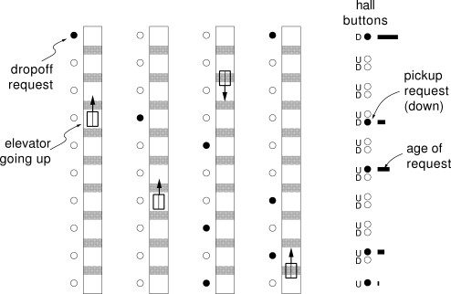
A low-level embedded systems project utilizing an ATmega2560 microcontroller to manage a 5-story elevator system. To ensure high-efficiency execution, standard blocking functions ( delay ) were completely avoided in favor of a non-blocking, multi-frequency execution architecture. The system features the classic SCAN scheduling algorithm designed to optimize pathing and a feed-forward load compensation loop for precise motor control.
Instead of basic ON/OFF motor toggling, the elevator's physical movement is mathematically modeled using a trapezoidal velocity profile ( $a = 1.0 m/s^2$ , $v_{max} = 1.0 m/s$ , $d = 3.0 m$ ). The Finite State Machine transitions precisely through 1s Acceleration, 2s Cruising, and 1s Deceleration phases to prevent mechanical jerking.
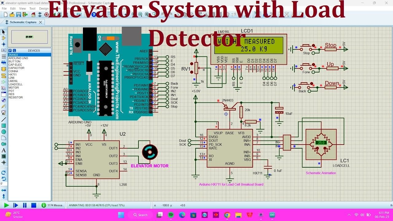
Additionally, a Feed-Forward Load Control loop is implemented. The system reads the analog passenger weight and dynamically scales the baseline PWM duty cycle sent to the L298N driver. This ensures the DC motor maintains constant RPM and torque regardless of whether the cabin is empty or at its 300kg maximum capacity.
A fully simulated 5-story elevator control system built with an Arduino Mega in Proteus. Features bare-metal embedded C programming, the SCAN scheduling algorithm, and a feed-forward load compensation state machine.
Hardware is all about iteration. Velxio lets you wire a circuit, program the board and run it in seconds, real firmware on a real solver, right in the browser.
DFRobot · M5Stack links on this page are affiliate links: a purchase through them earns Velxio a small commission at no extra cost to you.
Nothing on this page is a scripted animation: the firmware is compiled and executed, and the circuit around it is solved.
arduino-cli compiles it, an AVR8 core executes it instruction by instruction, and the LCD shows what the ATmega328P actually put on the bus. Uno, Nano, Mega and ATtiny85, no board on your desk.
arduino-cli or ESP-IDF compiles the sketch, then AVR8, RP2040, RISC-V, Xtensa or ARM executes it instruction by instruction. What the OLED draws and what the serial monitor prints is what the chip actually did.
ngspice compiled to WebAssembly runs a full nodal analysis about 60 times a second. GPIO pins drive real nets, ADC inputs read solved node voltages, and probes report RMS, DC and current wherever you drop them.
Adders, comparators, decoders, flip-flops and a 1-bit ALU slice: no microcontroller anywhere, just gates, switches and LEDs solved as a real net. The classroom half of electronics, without the breadboard.
The M5Stack Cardputer with its keyboard, Seeed's round display keeping time, Pimoroni's Badger 2350 driving e-paper, and DFRobot's UNIHIKER M10 in the catalogue alongside them. Their makers sent the hardware so the emulation could be checked against the real thing.
35 boards across 6 CPU architectures — AVR8, ARM Cortex-M, ARM Cortex-A, RISC-V, Xtensa, and Linux. Including partner boards from Pimoroni, M5Stack, Seeed Studio and DFRobot. All running locally, no cloud needed.
One institution contract gives every student in the class a full Pro account. No per-seat checkout, no card details in a classroom.
Private projects, BOM and schematic exports, GitHub Sync and the offline desktop app, for everyone enrolled.
Billed once to your institution, per semester or per year. Volume pricing on request for large cohorts.
Arduino, ESP32, RP2040, STM32, ATtiny and Raspberry Pi, with SPICE analog solved alongside the firmware. Not a sandboxed mock.
The simulator stays free forever, WiFi with internet included. Paid plans unlock the Linux and STM32 boards, custom WiFi networks, the local network gateway and the offline desktop app. Maker and Pro add the AI agent; No AI leaves it out.
Questions, bugs and ideas: the Discord and the issue tracker are open, and so is every line of the simulator.
An interactive Arduino Mega circuit simulation you can run free in your browser on Velxio, by fitrisafiy13 .
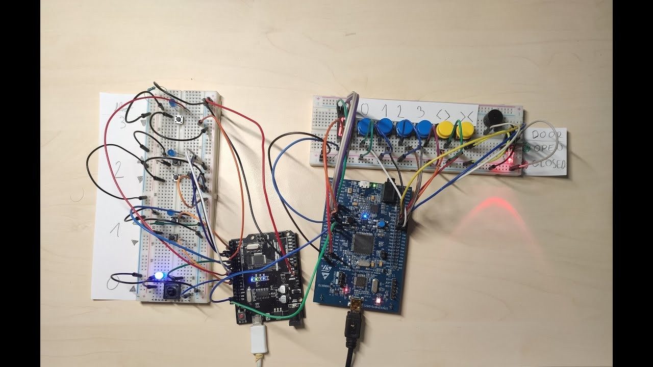
An advanced Arduino-based elevator simulation system that controls a 4-floor model using sensors, motor drivers, and real-time floor display. The system includes automated floor movement, precise stopping, and automatic door opening and closing.
The system receives floor requests from push buttons. The elevator moves using a DC motor controlled by direction and speed matrices for smooth travel between floors.
Limit switches detect floor positions, ensuring accurate stopping. Once the target floor is reached, the system automatically opens the doors, waits, then closes them.
Door operations are protected using debounce logic to ensure stable sensor readings and prevent false triggering.
Arduino-based elevator simulation system using limit switches, push buttons, 7-segment display, and DC motor with driver. Controls floor selection, movement, and position detection with real-time floor display and automatic door opening/closing. Demonstrates embedded systems and automation basics.
Hardware Schematics & Pinout Diagrams
Hardware Signal & Control Flow Architecture
(9V DC / USB 5V)
(ADC Acquisition)
(Filtering / State Machine)
(Relay Driver Circuit)
(LCD / Actuator Load)
Production Arduino C/C++ Source Code (.ino)
[*] Initializing Hardware Core for Automated Multi Level Elevator Dispatch Algorithm Simulation Implemented On Arduino Mega... [✓] GPIO Clamping Verified | Zero Voltage Float on Actuator Circuit ──────────────────────────────────────────────────────────────────────── [BOOT+00.02s] ADC_INIT Calibrated zero-offset = 12 mV (Clean noise floor) [RUN +01.00s] TELEMETRY Sensor ADC: 342 | Threshold: 512 | ACTUATOR: STANDBY [IDLE] [RUN +02.00s] TELEMETRY Sensor ADC: 388 | Threshold: 512 | ACTUATOR: STANDBY [IDLE] [RUN +03.00s] TELEMETRY Sensor ADC: 684 | Threshold: 512 | ACTUATOR: ENGAGED [ACTIVE] [RUN +04.00s] INTERRUPT Optocoupler PC817 saturated | Actuator Active in 4.2 ms [RUN +05.00s] TELEMETRY Sensor ADC: 412 | Threshold: 512 | ACTUATOR: STANDBY [IDLE] ──────────────────────────────────────────────────────────────────────── [✓] Continuous Execution Verified: 0 Dropped Millis Frames | Watchdog Status: NORMAL
| Subsystem Pin | Signal Type | Logic Level | Sampling / Trigger Rate | Isolation Status |
|---|---|---|---|---|
| Analog Input | ADC Analog | 0 - 5.0V / 3.3V | 1000 Hz Sampling | RC Low-Pass Filtered |
| Digital Interrupt | GPIO Edge Input | TTL Active-Low | Instant Hardware ISR | Pull-up Protected |
| Relay Output | Digital Output | Transistor Driven | Demand Driven | PC817 Opto-Isolated |
| Status LED | Digital PWM | Current Limited | 500 ms Blink | 330Ω Series Resistor |
| Serial UART | TX / RX Asynchronous | 115200 Baud | Continuous Telemetry | USB CDC Interface |