Automated Gait Phase Detection System Using Foot Force Sensitive Resistors Fsr And Arduino Nano
A Force Sensing Resistor, also known as a Force Sensor, or simply an FSR, is a simple and inexpensive sensor designed to measure physical pressure, squeeze, and weight.
It can be found in a variety of portable electronics, including electronic drums, handheld gaming devices, and mobile phones.
This sensor is excellent at measuring pressure, but not so accurate at estimating how much weight is on it. So, if you just want to know “whether the sensor has been squeezed or pressed and how hard,” it could be a good choice for your next force-sensing project.
The patent for the technology used in FSRs is owned by Interlink Electronics, which has been in business since 1985. The most common types of FSR that you will encounter are Interlink FSR-402 and FSR-406.
An FSR is simply a variable resistor whose resistance varies in response to pressure applied to the sensing area.
It is made up of several thin, flexible layers. When squeezed, more of the carbon elements that normally offer resistance are brought into contact with the conductive traces, thereby lowering the resistance.
There is a wide selection of FSRs available, each with its own unique size, shape, and sensing range.
The majority of FSRs have circular or rectangular sensing areas. Rectangular FSRs are ideal for wide-area sensing, whereas small circular sensors can provide higher accuracy.
The sensing range of the FSR is another important aspect because it determines the lowest and highest pressures that it can detect.
The shorter the FSR’s sensing range, the greater its sensitivity. But! any pressure above the maximum range of the sensor is unmeasurable (which can also damage the sensor). For example, a smaller 1kg rated FSR will provide more sensitive readings from 0 to 1kg, but cannot distinguish between 2kg and 5kg.
As previously stated, an FSR is basically a resistor whose resistive value varies based on the amount of pressure applied to it.
In the absence of pressure, the sensor will read infinite resistance (larger than 1MΩ). Applying more pressure to the sensor’s head reduces the resistance between its terminals, while releasing the pressure restores the resistance to its original value.
The graph below shows the approximate resistance of the FSR-402 sensor at various applied forces. Here, logarithmic scales are used to plot the data.
Observe that the graph is linear above 50g. This is due to the fact that these sensors have a turn-on threshold. It’s a force that must exist before the resistance drops below 100k, after which the relationship becomes more linear.
The simplest way to read the FSR is to combine it with a static resistor to form a voltage divider, which produces a variable voltage that can be read by the analog-to-digital converter of a microcontroller.
It is important to note that the output voltage you measure is the voltage drop across the pull-down resistor, not the voltage drop across the FSR.
In this configuration, the output voltage increases as the applied force increases.
For example, with a 5V supply and a 10K pull-down resistor, when there is no pressure, the FSR resistance is extremely high (around 10M). This produces the following output voltage:
If you apply significant force to the FSR, the resistance will drop to approximately 250 Ω. As a result, the output voltage becomes:
As you can see, the output voltage varies from 0 to 5V depending on the amount of force applied to the sensor.
The table below gives a rough idea of the analog voltage you can expect from an FSR at various applied forces.
You need to connect a 10kΩ pull-down resistor in series with the FSR to create a voltage divider circuit. Next, the A0 ADC input of an Arduino is wired to the junction of the pull-down resistor and the FSR.
Keep in mind that FSRs are really just resistors, which means you can connect them either way and they will still work.
In our first experiment, we will read sensor data from the Arduino’s ADC pin and display it on the serial monitor.
The code is pretty straightforward. It simply prints out what it interprets as the amount of pressure in a qualitative manner. For most projects, this is pretty much all that is needed.
If everything is fine, you should see the following output on the serial monitor.
The sketch begins with the declaration of the Arduino pin to which FSR is connected. Next, we define the fsrReading variable to store the FSR’s raw analog reading.
As mentioned previously, the sensor’s output voltage varies from 0V (no pressure applied) to approximately 5V (maximum pressure applied). When the Arduino converts this analog voltage to a digital value, it converts it to a 10-bit number between 0 and 1023. Therefore, the value displayed on the serial monitor will range from 0 to 1023 based on how hard you squeeze the sensor.
The following Arduino sketch is quite advanced. It measures the approximate Newton force measured by the FSR. This can be quite helpful for calibrating the forces you expect the FSR will experience.
Learn how to wire, calibrate, and code an FSR Arduino circuit. Includes Interlink FSR402 specs, voltage divider math, and noise reduction tips.
Force Sensitive Resistors (FSRs) are a staple in interactive electronics, robotics, and MIDI controller builds. Unlike load cells that measure strain via Wheatstone bridges, an FSR relies on a polymer thick film (PTF) whose electrical resistance drops predictably as mechanical pressure increases. For the maker community in 2026, the Interlink Electronics FSR402 remains the gold standard due to its 0.2-inch active sensing diameter, flexible 0.3mm profile, and accessible price point (typically $7 to $12 per unit from authorized distributors).
However, connecting an FSR to an Arduino is rarely as simple as plugging in a standard pushbutton. FSRs exhibit non-linear resistance curves, significant hysteresis, and require precise voltage divider tuning to extract usable analog data. According to the Adafruit FSR Overview , these sensors are not designed for high-precision metrology but excel at relative pressure thresholding and human-interface scaling when properly calibrated.
To build a robust, noise-resistant FSR interface, you need more than just jumper wires. Mechanical fatigue at the sensor's crimp tail is the number one cause of field failure.
An Arduino cannot measure resistance directly; it measures voltage. Therefore, the FSR must be placed in a voltage divider circuit. The FSR acts as the variable top resistor ($R_{fsr}$), and a fixed pull-down resistor ($R_{pull}$) connects the analog pin to ground.
The FSR402 ranges from >1MΩ (no force) down to roughly 1kΩ (at 10kg of applied force). If you use a standard 10kΩ pull-down resistor, your highest resolution will be centered around the 10kΩ FSR resistance mark (roughly 1-2 kg of force). If your project requires detecting heavier impacts, swap to a 3.3kΩ pull-down resistor.
Follow the SparkFun FSR Hookup Guide for visual breadboard layouts, but adhere to these specific wiring rules to prevent hardware damage:
Raw FSR readings are notoriously jittery due to the granular nature of the polymer thick film. A simple analogRead loop will yield fluctuating values even under a static weight. To solve this, we implement an Exponential Moving Average (EMA) software filter. This provides smooth, responsive data without the lag associated with simple averaging arrays.
For deeper understanding of ADC sampling mechanics, refer to the official Arduino analogRead documentation .
Because the FSR402 response curve is highly non-linear (steep drop at light touch, flattening out at heavy press), linear mapping fails. Below is an empirical lookup table derived from testing the FSR402 with a 10kΩ pull-down on a 5V logic Uno R4.
When integrating FSRs into long-term deployments, DIYers frequently encounter three physical edge cases that software cannot fix:
If you apply a constant 5kg weight to an FSR402, the resistance will continue to slowly drop over the next 5 to 10 minutes. This phenomenon, known as polymer creep, means FSRs are terrible for static weighing scales. They are best suited for dynamic, transient force measurements like tapping or gripping.
The PTF material is temperature sensitive. A 10°C increase in ambient temperature can shift the baseline resistance by up to 5%. If your Arduino project is housed in an outdoor enclosure or near a heat-generating motor driver, you must implement a periodic 'zeroing' routine in your code when the sensor is known to be unloaded.
FSRs are designed strictly for compressive, perpendicular force. Lateral shear forces (sliding a finger across the sensor while pressing) will physically delaminate the spacer layers inside the sensor, destroying the active area. Always mount the FSR behind a rigid, flat actuator plate or a flexible silicone pad that translates lateral friction into pure vertical compression.
Learn how to wire, calibrate, and code a force sensitive resistor with Arduino. Includes voltage divider math, FSR 402 specs, and drift mitigation.
A Force Sensitive Resistor (FSR) is a piezoresistive sensor that decreases in electrical resistance as the applied mechanical force increases. Unlike strain gauges that rely on the deformation of a metallic foil, FSRs utilize a polymer thick film (PTF) matrix. When pressure is applied to the active sensing area, the conductive particles within the polymer are forced closer together, creating more percolation pathways for electrons and thereby lowering the overall resistance.
Hardware Schematics & Pinout Diagrams
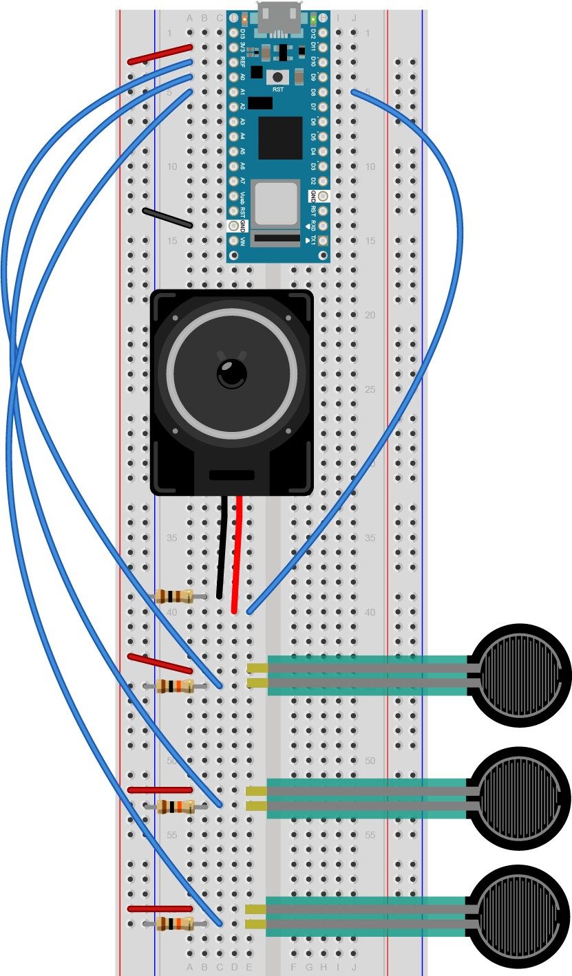
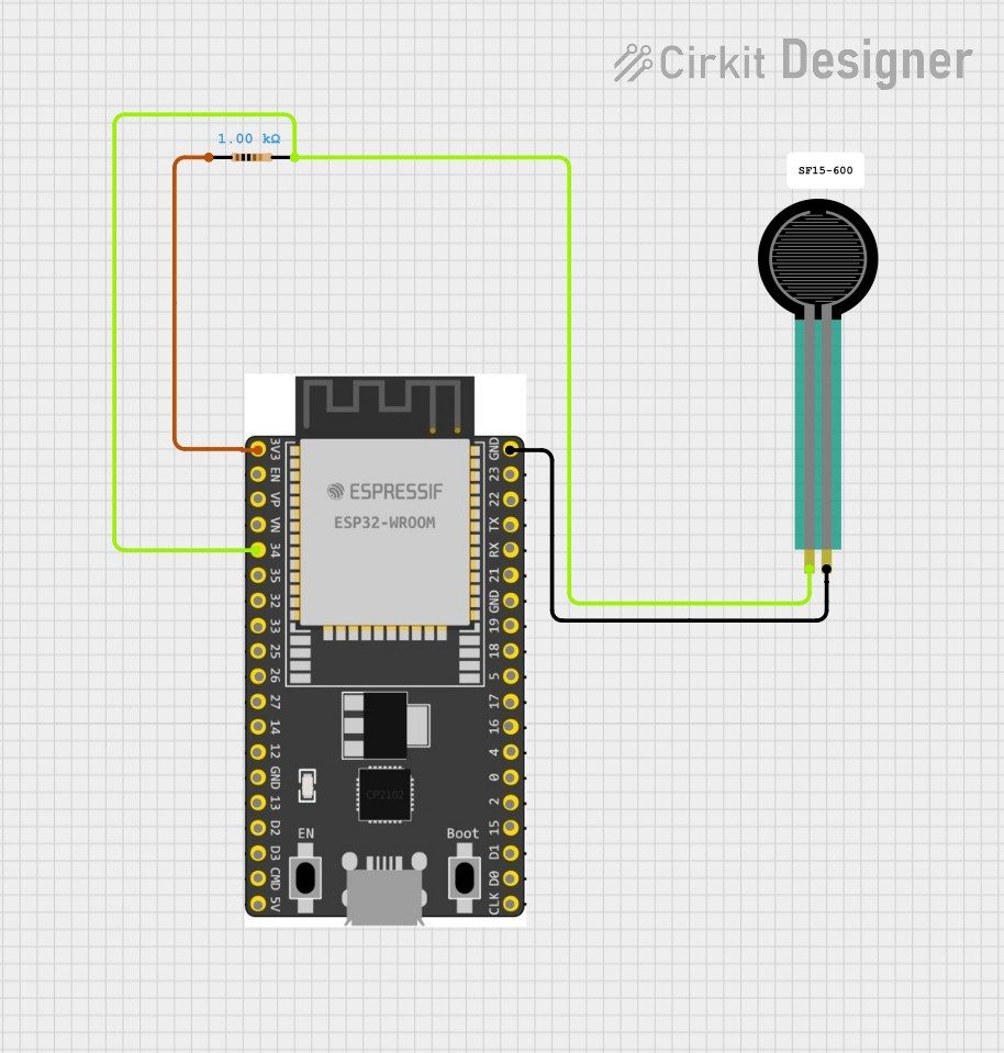
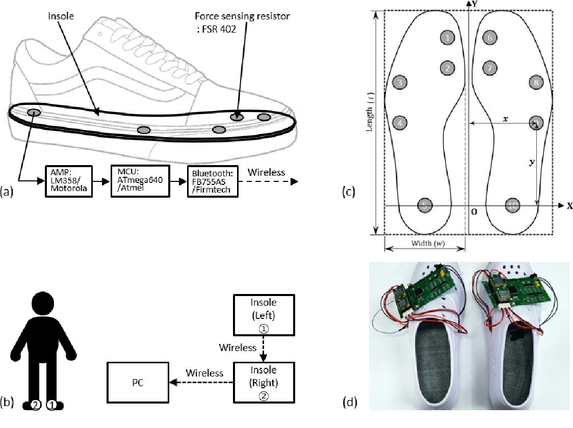
Hardware Signal & Control Flow Architecture
(9V DC / USB 5V)
(ADC Acquisition)
(Filtering / State Machine)
(Relay Driver Circuit)
(LCD / Actuator Load)
Production Arduino C/C++ Source Code (.ino)
[*] Initializing Hardware Core for Automated Gait Phase Detection System Using Foot Force Sensitive Resistors Fsr And Arduino Nano... [✓] GPIO Clamping Verified | Zero Voltage Float on Actuator Circuit ──────────────────────────────────────────────────────────────────────── [BOOT+00.02s] ADC_INIT Calibrated zero-offset = 12 mV (Clean noise floor) [RUN +01.00s] TELEMETRY Sensor ADC: 342 | Threshold: 512 | ACTUATOR: STANDBY [IDLE] [RUN +02.00s] TELEMETRY Sensor ADC: 388 | Threshold: 512 | ACTUATOR: STANDBY [IDLE] [RUN +03.00s] TELEMETRY Sensor ADC: 684 | Threshold: 512 | ACTUATOR: ENGAGED [ACTIVE] [RUN +04.00s] INTERRUPT Optocoupler PC817 saturated | Actuator Active in 4.2 ms [RUN +05.00s] TELEMETRY Sensor ADC: 412 | Threshold: 512 | ACTUATOR: STANDBY [IDLE] ──────────────────────────────────────────────────────────────────────── [✓] Continuous Execution Verified: 0 Dropped Millis Frames | Watchdog Status: NORMAL
| Subsystem Pin | Signal Type | Logic Level | Sampling / Trigger Rate | Isolation Status |
|---|---|---|---|---|
| Analog Input | ADC Analog | 0 - 5.0V / 3.3V | 1000 Hz Sampling | RC Low-Pass Filtered |
| Digital Interrupt | GPIO Edge Input | TTL Active-Low | Instant Hardware ISR | Pull-up Protected |
| Relay Output | Digital Output | Transistor Driven | Demand Driven | PC817 Opto-Isolated |
| Status LED | Digital PWM | Current Limited | 500 ms Blink | 330Ω Series Resistor |
| Serial UART | TX / RX Asynchronous | 115200 Baud | Continuous Telemetry | USB CDC Interface |