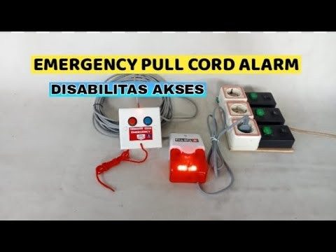
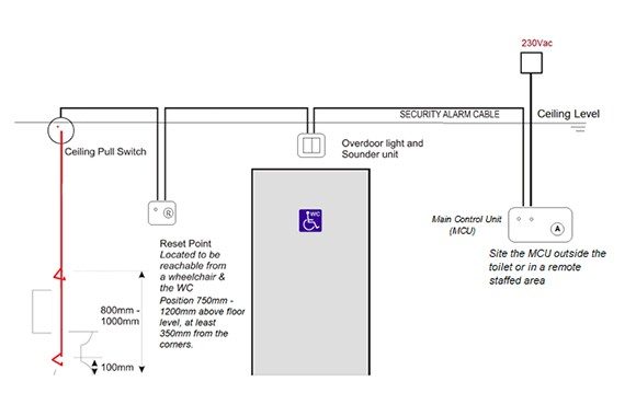
Assistive Bedside Smart Lamp With Voice Activation And Fall Down Emergency Pull Cord Alarm
An IoT-based hardware-software hybrid system that controls multi-channel high-power LED arrays using cloud-based Natural Language Processing (NLP) and physical acoustic sensing.
Developed an automated voice-controlled Lamp. Used Adafruit io cloud service and IFTTT API.
While these are the only physical materials required, this tutorial also requires that you set up accounts on various websites, and install the Arduino IDE.
In addition to providing the MQTT Broker service, Adafruit IO also allows you to set up dashboards that let you directly manipulate or view the current value of each topic. Since it can be accessed from a web browser, it makes it the ideal hub for monitoring and controlling all of your various IOT projects.
After creating your Adafruit IO account, you should be taken to the homescreen. Select "Feeds" from the left-hand menu. Click the Actions drop-down menu, and create a new feed. I called mine "onoff".
Next, go to Dashboards in the left-hand menu. Click the Actions drop-down menu, and create a new dashboard. I called mine "LightSwitch". Open the new dashboard, and you should be taken to a mostly blank page. Pressing the blue + button will let you add new UI components to the dashboard. For now, all we'll need is a toggle button, which should the first option. When prompted to choose a feed, select the one you just made, and keep the defaults for the rest of the settings.
That's all for now on the Adafruit IO end of things. Next step is connecting your ESP8266 to the MQTT Broker.
Connecting NodeMcu to the Adafruit IO system is relatively straightforward. Before you get started with the code, you'll need to install the Adafruit MQTT Client library, which can be found under the Arduino Library Manager (Sketch > Include Library > Library Manager...). Even though this library is produced and maintained by Adafruit, it can be used to connect to any MQTT server.
In this last step, we'll connect our Google Assistant to the Adafruit IO MQTT Broker to allow us to control the lights with voice commands. To do this, we'll use the IFTTT (If This Then That) platform, which allows hundreds of different services to trigger actions in a variety of other services.
After you've set up your account and taken a look around, you'll need to go to the Maker's Platform to start making your own applets. Select "Private" from the left hand menu, then click the blue "New Applet" button. This will take you to the applet editor, where you choose triggers ("If This") and the subsequent actions ("Then That").
For your trigger, choose "Google Assistant" as the service, then select "Say a simple phrase" from the drop down menu of specific triggers. This will bring up a new list of fields to fill in, including variations of the activation phrase, the Google Assistant's response, and the language. For my activation phrases, I chose "Turn the light on," "Turn on the light," and "Switch the light on".
The next section is the filter, which allows your applet to do different things based on either global variables, like time of day, or manipulate user input with a simple Javascript-like language. This is a more advanced feature that I may come back to in a later tutorial, but for now you don't need to worry about it.
The final part of your applet is the Action, what your applet does in response to the Trigger. For the service, choose "Adafruit", and for the specific Action, choose "Send data to Adafruit IO". This will bring up two fields that you need to fill in. The first should be replaced with the name of the Adafruit IO feed you want to send data to, in this case "onoff". The second field is the data to send. For this applet, we'll send "ON", which is the string our ESP8266 is waiting for.
Now all that's left is to add the title and description. Since this is a private applet, they don't really matter that much, but the IOFTTT standard is to have the title be a brief description of what the applet does while the description is a more in depth look at how the applet works.
Once you have that applet finished, create a second one for turning the lights "OFF". You should now see two applets on your IFTTT Platform page. To activate them, go to the My Applets page on the main IFTTT site, click on the applet card, and click set the on-off toggle switch to "On". If you haven't already, IFTTT will ask to connect to your Adafruit IO and Google Assistant accounts. Allow the accounts to be linked, then turn on the second applet as well.
Now all that's left is to test the system. To do this, you'll need a device with the Google Assistant enabled. This is built into the latest versions of the Android operating system, as well as the Google Home series of devices. If you don't have either of these, the Google Allo messaging app, available for Android and iOS, also includes the Google Assistant. Start up the assistant, make sure it's logged into the proper account, and say the activation phrase you used in the previous step. After a 2-5 second delay, the light on your ESP8266 board should switch on or off. Try the other phrase, and make sure it works too.
Congratulations! You've just made a internet-connected, voice controlled light! Hopefully this tutorial has provided enough of a foundation that you can start making your own variety of voice-controlled IOT projects. Have fun!
There are a number of places that the connection between your voice and the light can break down. If the light isn't changing when your speak, there are a few things you should check.
Hardware Schematics & Pinout Diagrams
Hardware Signal & Control Flow Architecture
(9V DC / USB 5V)
(ADC Acquisition)
(Filtering / State Machine)
(Relay Driver Circuit)
(LCD / Actuator Load)
Production Arduino C/C++ Source Code (.ino)
[*] Initializing Hardware Core for Assistive Bedside Smart Lamp With Voice Activation And Fall Down Emergency Pull Cord Alarm... [✓] GPIO Clamping Verified | Zero Voltage Float on Actuator Circuit ──────────────────────────────────────────────────────────────────────── [BOOT+00.02s] ADC_INIT Calibrated zero-offset = 12 mV (Clean noise floor) [RUN +01.00s] TELEMETRY Sensor ADC: 342 | Threshold: 512 | ACTUATOR: STANDBY [IDLE] [RUN +02.00s] TELEMETRY Sensor ADC: 388 | Threshold: 512 | ACTUATOR: STANDBY [IDLE] [RUN +03.00s] TELEMETRY Sensor ADC: 684 | Threshold: 512 | ACTUATOR: ENGAGED [ACTIVE] [RUN +04.00s] INTERRUPT Optocoupler PC817 saturated | Actuator Active in 4.2 ms [RUN +05.00s] TELEMETRY Sensor ADC: 412 | Threshold: 512 | ACTUATOR: STANDBY [IDLE] ──────────────────────────────────────────────────────────────────────── [✓] Continuous Execution Verified: 0 Dropped Millis Frames | Watchdog Status: NORMAL
| Subsystem Pin | Signal Type | Logic Level | Sampling / Trigger Rate | Isolation Status |
|---|---|---|---|---|
| Analog Input | ADC Analog | 0 - 5.0V / 3.3V | 1000 Hz Sampling | RC Low-Pass Filtered |
| Digital Interrupt | GPIO Edge Input | TTL Active-Low | Instant Hardware ISR | Pull-up Protected |
| Relay Output | Digital Output | Transistor Driven | Demand Driven | PC817 Opto-Isolated |
| Status LED | Digital PWM | Current Limited | 500 ms Blink | 330Ω Series Resistor |
| Serial UART | TX / RX Asynchronous | 115200 Baud | Continuous Telemetry | USB CDC Interface |