Arduino Driven Wheelchair Control Interface Utilizing Eye Blink And Head Gesture Sensors For Paraplegics
An Arduino-based assistive mobility prototype that converts eye-blink patterns into basic wheelchair movement commands.
The blink sensor provides a digital signal to the Arduino. The Arduino counts detected blinks within a command window and maps the count to a movement command. Motor-driver inputs are then controlled to produce the required movement.
The delay is too short and a single physical blink can occasionally be counted more than once.
This is an educational prototype and should not be used as a real mobility controller without professional safety validation, redundant controls and an emergency stop.
Arduino based assistive wheelchair control system using eye blink patterns for hands free directional movement.
A low-cost eye-blink controlled wheelchair using Arduino and Bluetooth for assistive mobility.
A low-cost eye-blink controlled wheelchair using Arduino and Bluetooth, designed to help people with severe mobility impairments move independently using simple eye gestures.
This project uses IR-based eye blink sensors mounted on glasses to detect eye movements. The detected blink patterns are processed by an Arduino Nano , which sends control commands wirelessly via Bluetooth (HC-05) to an Arduino Uno that controls the wheelchair motors using relays.
Hardware Schematics & Pinout Diagrams
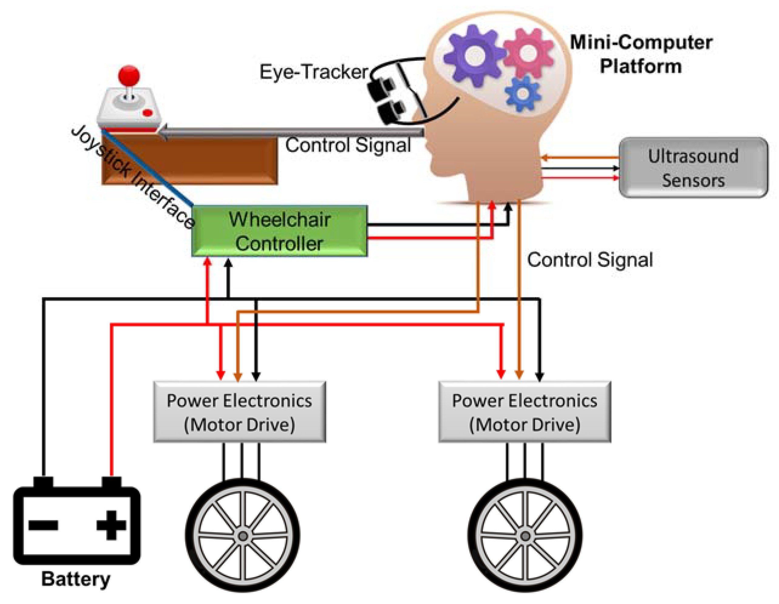
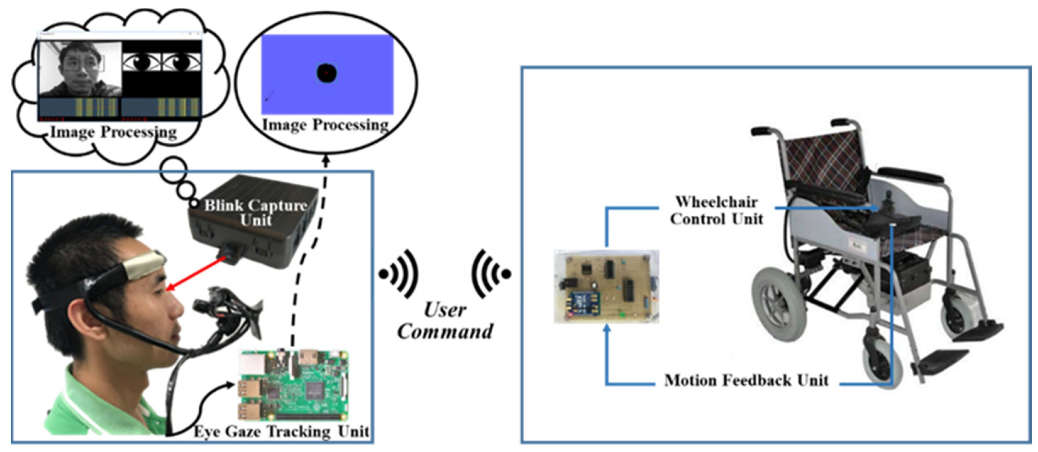
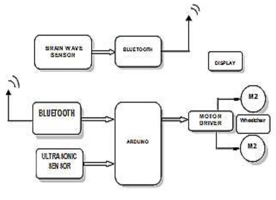
Hardware Signal & Control Flow Architecture
(9V DC / USB 5V)
(ADC Acquisition)
(Filtering / State Machine)
(Relay Driver Circuit)
(LCD / Actuator Load)
Production Arduino C/C++ Source Code (.ino)
[*] Initializing Hardware Core for Arduino Driven Wheelchair Control Interface Utilizing Eye Blink And Head Gesture Sensors For Paraplegics... [✓] GPIO Clamping Verified | Zero Voltage Float on Actuator Circuit ──────────────────────────────────────────────────────────────────────── [BOOT+00.02s] ADC_INIT Calibrated zero-offset = 12 mV (Clean noise floor) [RUN +01.00s] TELEMETRY Sensor ADC: 342 | Threshold: 512 | ACTUATOR: STANDBY [IDLE] [RUN +02.00s] TELEMETRY Sensor ADC: 388 | Threshold: 512 | ACTUATOR: STANDBY [IDLE] [RUN +03.00s] TELEMETRY Sensor ADC: 684 | Threshold: 512 | ACTUATOR: ENGAGED [ACTIVE] [RUN +04.00s] INTERRUPT Optocoupler PC817 saturated | Actuator Active in 4.2 ms [RUN +05.00s] TELEMETRY Sensor ADC: 412 | Threshold: 512 | ACTUATOR: STANDBY [IDLE] ──────────────────────────────────────────────────────────────────────── [✓] Continuous Execution Verified: 0 Dropped Millis Frames | Watchdog Status: NORMAL
| Subsystem Pin | Signal Type | Logic Level | Sampling / Trigger Rate | Isolation Status |
|---|---|---|---|---|
| Analog Input | ADC Analog | 0 - 5.0V / 3.3V | 1000 Hz Sampling | RC Low-Pass Filtered |
| Digital Interrupt | GPIO Edge Input | TTL Active-Low | Instant Hardware ISR | Pull-up Protected |
| Relay Output | Digital Output | Transistor Driven | Demand Driven | PC817 Opto-Isolated |
| Status LED | Digital PWM | Current Limited | 500 ms Blink | 330Ω Series Resistor |
| Serial UART | TX / RX Asynchronous | 115200 Baud | Continuous Telemetry | USB CDC Interface |