Arduino Driven Robotic Telescope Mount With Real Time Celestial Object Tracking Algorithms
This project aims an automatic control for telescopes , is based on Arduino and is low-cost !
The control utilizes a calibration method and various settings which enable you to control any type of mount (not just equatorial and altazimuthal) pointed at any direction.
The total cost of upgrading your mount should be around 75 USD ( SkyWatcher SynScan GOTO Upgrade for EQ3-2 costs around 460 USD ).
See future work for missing features (like communication via USB or Bluetooth). Some implemented and working freatures:
You should add the four resistors between STEP - GND and DIR - GND pins to avoid a jitter of stepper motors at startup.
A typical extender for A4988 has an ENABLE pin, however, we do not need it. Instead, we need a pin for controlling microstepping . That is why you should hardwire the three microstepping pins and you should add a single pin to control them. Search for microstepping resolution truth table of A4988.
A cheap IR remote control might have a weak diode . In that case, you won’t be able to control the mount from a distant places. So I recommend you to replace the diode with a better one.
You also need to tune potentiometers of stepper drivers . Search for How to set output current limit on A4988 stepper driver . This can reduce noise produced by the motors or you can remove problems with skipping of steps .
The following list contains libraries you will need to sucessfuly compile the Star Tracker project (most of them is included in the Arduino IDE by default):
Next, you should modify the src/config.h file to fit your needs. Familiarize yourself with all the definitions in the file. You should definitely change LONGITUDE , LATITUDE , REDUCTION_RATIO_xx and DEG_PER_MOUNT_REV_xx variables! You also need to change DEFAULT_POLE_xx if you use an altazimuthal mount.
You may encounter a problem with stucked motors . In that case, I advice you to adjust ACCEL_STEPS_xx , ACCEL_DELAY_xx , FAST_DELAY_START_xx and FAST_DELAY_END_xx . Change these definitions in order to change motors speed or ac/deceleration.
You need to change definitions of key codes to fit the protocol used by your favourite remote control. Take look at the beginning of the src/keypad.h file. There are few definitions of KP_KEY_xx where xx describes the particular key. To figure out codes used by your remote control , upload the following sketch to your Arduino:
Then open the Serial monitor and observe the key codes of pressed keys. Note that you will receive 0xFFFFFFFF when you hold a key continuously.
You can also change mapping of these keys to particular actions in the src/control.h file (but be careful as these keys and actions should not cause conflicts and ambiguity).
Take an empty and formatted microSD card and copy there the content of the SD directory. It should be a single file catalog.csv which is a limited version of Stellarium catalogue of deep space objects . You can delete or add object to this file, however the structure and meaning of columns should be preserved.
The src/rtc_ds3231.h file contains implementation of Clock class for DS3231 module. In case you use other module or you want to obtain time from NTP servers, implement the Clock interface and change some lines in Star_Tracker.ino .
Similarly, you may need to change the implementation of the camera trigger control. The src/CanonEOS1000D.h file contains implementation of CameraController class for Canon EOS1000D . If you have other camera with other trigger logic , you should create a new implementation of CameraController and change some lines at Star_Tracker.ino . Note that in this case, you may also need a different wiring!
The only loss of precision is caused by Arduino’s floating point unit which cannot work with 64-bit floating point numbers. Especially while computing extremal values of some goniometric funcions (tangens and other functions which are reduced to computing tangens). These problems can occur while pointing to stars near celestial pole. The GoTo feature can miss few arc minutes and alignement can be imprecise in that case. However points with lower DEC values should be handled properly.
The tracking with very badly aligned mount can also be imprecise after some time because the speeds of DEC and RA motors are computed just once at the start of the movement. Unfortunately these speeds does not have to be constant necessarily.
This project is a personal DIY build of a motorized telescope mount that combines embedded hardware, motion control, and Python-based tracking logic. The aim is to make a telescope more interactive and practical by allowing it to move in altitude and azimuth, either manually with a joystick or automatically based on calculated target positions.
It started as a hands-on electronics and firmware project and grew into a small but complete system for experimenting with positioning, control loops, and basic astronomy-driven movement.
This repository brings together the pieces needed to operate a simple robotic telescope setup:
The system is split between hardware control on the Arduino and higher-level logic in Python.
This makes the project a nice mix of embedded programming, sensor interfacing, and practical control engineering.
This repository is best viewed as an experimental, hands-on engineering project that grows from simple movement tests into a more complete telescope control system.
A system that tracks and predicts the real-time location of celestial objects with simplified calculations and component setup. To view the project demo and the computations, please click here .
Calibrate Motors : Test and ensure both motors move in the correct direction for positive and negative angles. If the movement is incorrect, swap the motor connections and re-test.
Debug Serial Communication : Use the Arduino IDE's Serial Monitor to verify that each Arduino correctly receives data from the Python program.
Reset for Errors : If any issue arises during tracking or prediction, press the Reset (D13) button to return to the main menu.
Check Hardware Connections : Ensure all wires and connections are secure. Verify that the power supply is adequate for the motors and servos.
Note : To enable the functionality of rotating the shaft anticlockwise for the altitude and azimuth stepper motors when pointing at celestial bodies or tracing their orbits, interchange the connections of the motor's input ports to the Arduino's Digital ports. Test-run the code to check if the motors move anticlockwise. Iterate until the desired movement is achieved. One of the motors must move anticlockwise for positive angles, and for negative angles, similarly.
A system that aims to track and predict the movements of celestial objects with a fair amount of accuracy.
Hardware Schematics & Pinout Diagrams
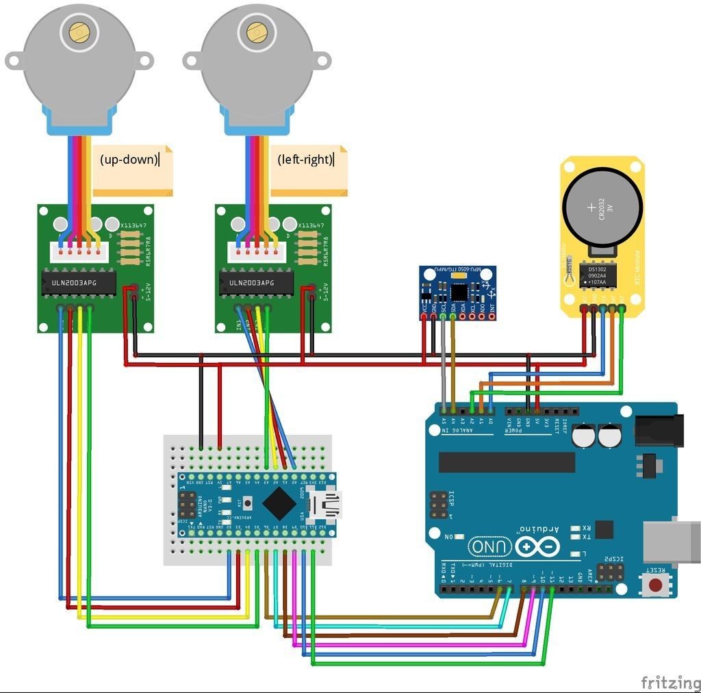
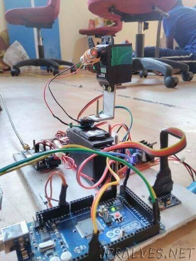
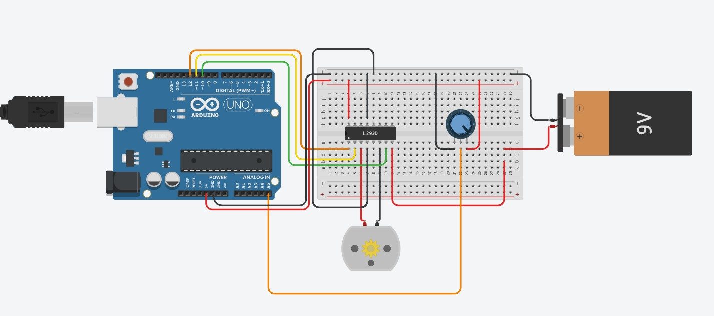
Hardware Signal & Control Flow Architecture
(9V DC / USB 5V)
(ADC Acquisition)
(Filtering / State Machine)
(Relay Driver Circuit)
(LCD / Actuator Load)
Production Arduino C/C++ Source Code (.ino)
[*] Initializing Hardware Core for Arduino Driven Robotic Telescope Mount With Real Time Celestial Object Tracking Algorithms... [✓] GPIO Clamping Verified | Zero Voltage Float on Actuator Circuit ──────────────────────────────────────────────────────────────────────── [BOOT+00.02s] ADC_INIT Calibrated zero-offset = 12 mV (Clean noise floor) [RUN +01.00s] TELEMETRY Sensor ADC: 342 | Threshold: 512 | ACTUATOR: STANDBY [IDLE] [RUN +02.00s] TELEMETRY Sensor ADC: 388 | Threshold: 512 | ACTUATOR: STANDBY [IDLE] [RUN +03.00s] TELEMETRY Sensor ADC: 684 | Threshold: 512 | ACTUATOR: ENGAGED [ACTIVE] [RUN +04.00s] INTERRUPT Optocoupler PC817 saturated | Actuator Active in 4.2 ms [RUN +05.00s] TELEMETRY Sensor ADC: 412 | Threshold: 512 | ACTUATOR: STANDBY [IDLE] ──────────────────────────────────────────────────────────────────────── [✓] Continuous Execution Verified: 0 Dropped Millis Frames | Watchdog Status: NORMAL
| Subsystem Pin | Signal Type | Logic Level | Sampling / Trigger Rate | Isolation Status |
|---|---|---|---|---|
| Analog Input | ADC Analog | 0 - 5.0V / 3.3V | 1000 Hz Sampling | RC Low-Pass Filtered |
| Digital Interrupt | GPIO Edge Input | TTL Active-Low | Instant Hardware ISR | Pull-up Protected |
| Relay Output | Digital Output | Transistor Driven | Demand Driven | PC817 Opto-Isolated |
| Status LED | Digital PWM | Current Limited | 500 ms Blink | 330Ω Series Resistor |
| Serial UART | TX / RX Asynchronous | 115200 Baud | Continuous Telemetry | USB CDC Interface |