Arduino Driven Driver Fatigue Warning System Monitoring Steering Wheel Grip Force Variations
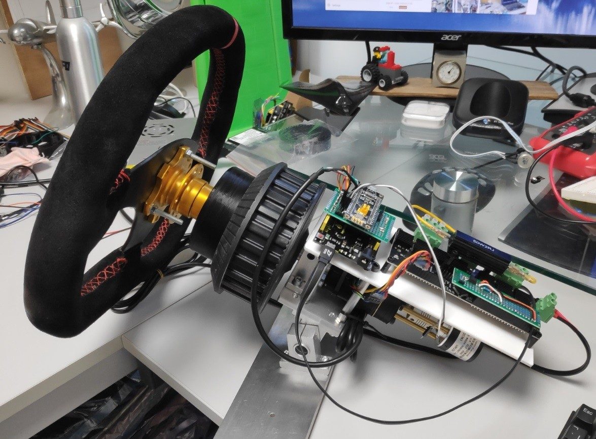
SafeSteer is a hybrid safety system designed to prevent accidents caused by driver drowsiness and sudden health issues (e.g., heart attacks or seizures). It combines grip sensors on a steering wheel with computer vision for robust driver monitoring.
If potential danger is detected, the system provides multi-sensory feedback (haptic vibration, buzzer alarms, visual LEDs) and can actively slow down the simulated vehicle motor.
The system employs a graduated response system to handle drowsiness or lack of control:
Drivers who are experiencing tiredness become large dangers to both themselves and anyone else around them on the road, as reaction times, concentration, and alertness are all greatly impaired. This is why Shebin Jose Jacob decided to create a drowsiness detection system that can accurately tell when someone behind the wheel is fatigued and should pull over for some rest.
The solution is comprised of a single Nicla Vision board , which contains a 2MP camera for collecting images, an IMU, microphone, distance sensor, and finally a dual Arm Cortex-M7/M4 processor for quickly running embedded machine learning models. Data for the project was gathered by taking many pictures and labeling the bounding boxes surrounding the eyes as either closed or open. From here, Jacob trained a FOMO-based (Faster Objects, More Objects) object recognition model on the sample images and was able to achieve an accuracy of 100%.
Live classifications from the Nicla Vision further reinforced the model’s stated accuracy, which meant Jacob could move onto the final step of creating his project. The tinyML model was deployed as a fully-contained Arduino library, meaning that all the code had to do is get a new image, run it through the object recognition model, and check the result. A label of closed eyes, therefore, causes a buzzer to sound and a red LED to illuminate.
More details on this potentially life-saving application can be found here in Edge Impulse’s blog post .
A compact edge AI solution to help keep you and your loved ones out of harm's way on those sweet long rides and weekend getaways.
I love long road trips on holidays with family or friends. But spending too long at the wheel leads to drowsiness and fatigue sooner or later. Unattentiveness of the driver is a major cause of road accidents. It is advised that a person spend no more than 6 hours a day driving. But there is not really a sure way to tell when a person is feeling tired, other than self-intuition, and that is no exact science, nor can it be relied upon to prevent mishaps.
So I decided to build an automatic solution, one which can monitor the driver continuously and alert them when it detects signs of losing concentration or attentiveness, advising the driver to take a break and rest. For this, I decided to use Infineon's development kits specially designed for edge AI applications, along with a small 2 MP camera module I had lying from a previous project, to quickly come up with a prototype application.
The PSoC™ 62S2 Wi-Fi BT Pioneer Kit ( CY8CKIT-062S2-43012) is a low-cost hardware platform that enables design and debug of the PSoC™ 62 MCU and the Murata 1LV Module (CYW43012 Wi-Fi + Bluetooth Combo Chip).
The IoT sense expansion kit is a low-cost Arduino™ UNO compatible shield board that can be used to easily interface a variety of sensors with the PSoC™ 6 MCU platform, specifically targeted for audio and machine learning applications.
The ESP32-CAM development board has a very competitive small-sized camera module board that can operate independently as a minimum system with a footprint of only 27*40. It comes with OV2640, a 2MP camera module.
I found a promising dataset and model for predicting driver drowsiness over at Kaggle and decided to use it for the first iteration of the project. The particular notebook is linked below:
The model works by extracting visual artefacts including the eyes and mouth of the driver from the camera frame, and classifying them as being open/close and whether the driver is yawning using a convolutional neural network (CNN).
On the particular dataset, an accuracy of 94.8% was achieved on the train set and 96.2% on the validation set. Further, the model was used to predict some unlabelled inputs from my webcam to a very good degree of accuracy.
The results of these classifications over time are then used as the basis for predicting the driver's alertness.
It provides an easy and interactive way to transform the Keras model file into an embedded C++ library. I used the Machine_Learning_Neural_Network_Profiler example to get started and recommend doing the same to follow along.
Using the ML Configurator tool, I generated the source code and validated it against the dataset. As the dataset consists of image data, I had to preprocess it separately into feature arrays before feeding it into the model.
To set up the input on ESP32-CAM module, I used Arduino IDE to program it. Pictures are taken from the OV2640 camera module at a frequency of 15 Hz. To relay the data to PSoC board, I opted to use I2C serial communication. Since both hardware I2C buses were already in use by the camera module, I used a soft I2C implementation using IO12 and IO13 pins.
The following tutorial explains how to get the ESP32 libraries working on the IDE. ESP32-CAM Video Streaming and Face Recognition with Arduino IDE | Random Nerd Tutorials
Use the AI-Thinker model for the part number. Connect pin IO0 to GND while flashing code to the module and disconnect it afterwards. I used an Arduino board to flash to the module but any USB-TTL device will work.
On the PSoC side, from the available GPIO pins I chose Serial Communication Block 0 for communication with ESP32, which were pins P02 and P03, as shown, as these were also readily exposed on the discovery board. Any other combination of pins can also be chosen, changing the code accordingly.
I referred the following page for information about pin configuration: MTB CAT1 Peripheral driver library: I2C (SCB) (infineon.github.io)
The sense expansion kit is easier to set up, as it can be directly mounted on the Arduino pin headers. To use the OLED display, the following libraries need to be added to the project: CY8CKIT-028-SENSE and emwin.
Finally, in main.c, include both of these libraries to get started with modifying the OLED display.
I initially planned to program the device to ping a Wifi network if the driver becomes drowsy. This would be intercepted by an Android application to further alert the driver using an alarm.
However, I didn't get to this part in time for the contest and will be updating this in the coming week.
For demonstration, I am streaming the video from my webcam instead of ESP32, which works quite similarly, to show the video stream being captured as well. The output from the application is also transmitted serially for display on the terminal.
I hope you enjoyed this project. Please leave behind any feedback in the comments.
Hardware Schematics & Pinout Diagrams
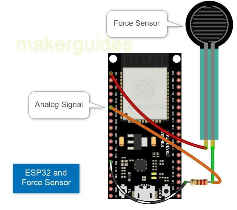
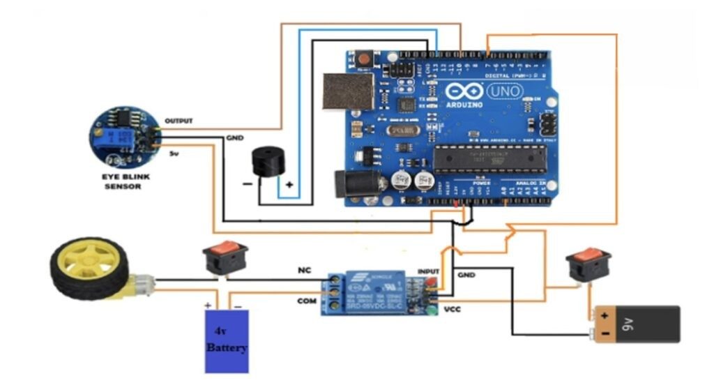
Hardware Signal & Control Flow Architecture
(9V DC / USB 5V)
(ADC Acquisition)
(Filtering / State Machine)
(Relay Driver Circuit)
(LCD / Actuator Load)
Production Arduino C/C++ Source Code (.ino)
[*] Initializing Hardware Core for Arduino Driven Driver Fatigue Warning System Monitoring Steering Wheel Grip Force Variations... [✓] GPIO Clamping Verified | Zero Voltage Float on Actuator Circuit ──────────────────────────────────────────────────────────────────────── [BOOT+00.02s] ADC_INIT Calibrated zero-offset = 12 mV (Clean noise floor) [RUN +01.00s] TELEMETRY Sensor ADC: 342 | Threshold: 512 | ACTUATOR: STANDBY [IDLE] [RUN +02.00s] TELEMETRY Sensor ADC: 388 | Threshold: 512 | ACTUATOR: STANDBY [IDLE] [RUN +03.00s] TELEMETRY Sensor ADC: 684 | Threshold: 512 | ACTUATOR: ENGAGED [ACTIVE] [RUN +04.00s] INTERRUPT Optocoupler PC817 saturated | Actuator Active in 4.2 ms [RUN +05.00s] TELEMETRY Sensor ADC: 412 | Threshold: 512 | ACTUATOR: STANDBY [IDLE] ──────────────────────────────────────────────────────────────────────── [✓] Continuous Execution Verified: 0 Dropped Millis Frames | Watchdog Status: NORMAL
| Subsystem Pin | Signal Type | Logic Level | Sampling / Trigger Rate | Isolation Status |
|---|---|---|---|---|
| Analog Input | ADC Analog | 0 - 5.0V / 3.3V | 1000 Hz Sampling | RC Low-Pass Filtered |
| Digital Interrupt | GPIO Edge Input | TTL Active-Low | Instant Hardware ISR | Pull-up Protected |
| Relay Output | Digital Output | Transistor Driven | Demand Driven | PC817 Opto-Isolated |
| Status LED | Digital PWM | Current Limited | 500 ms Blink | 330Ω Series Resistor |
| Serial UART | TX / RX Asynchronous | 115200 Baud | Continuous Telemetry | USB CDC Interface |