Arduino Controlled Bidirectional On Board Charger For Vehicle To Home V2h Power Delivery
Short Answer: Bidirectional Charging 101: Hardware, software, and battery health implications of using your EV to power your home through the ISO 15118-20 standard.
For most EV owners, their car represents the largest energy storage asset they will ever own. A typical long-range EV holds 75-100kWh of energy - enough to power a standard American home for three to five days. Yet, for years, that energy was "locked" inside the car, capable of moving wheels but unable to power a toaster.
Vehicle-to-Home (V2H) is the technology that allows an EV to reverse the flow of electricity, sending power back through the charger into the home's electrical panel. This guide explores the technical bridge between mobility and residency, deconstructing the standards and hardware that allow your car to function as a mobile microgrid.
In this model, the car's internal inverter (which usually converts grid AC to battery DC) is upgraded to work in reverse.
In this model, the car sends raw DC power from the battery directly to an external inverter sitting on your garage wall.
Communication is the most difficult part of V2H. The car and the charger must agree on voltage, current, and state-of-charge with microsecond precision to prevent a physical arc or battery damage.
The ISO 15118-20 standard, finalized and widely adopted in 2026, is the universal protocol for this conversation. It enables:
The #1 question from homeowners: "Will powering my house wear out my car battery?"
Most modern EV batteries (especially LFP) are rated for 300,000+ miles of driving (approx. 2,000 - 3,000 full cycles).
Most 2026 manufacturer warranties (Tesla, Ford, GM) now explicitly allow V2H usage as long as it doesn't exceed a specific annual throughput (e.g., 2MWh per year).
To enable V2H today, you need more than just a car and a plug. You need a Home Integration System .
In 2026, many owners get confused by the different "V-to-somthing" acronyms. Understanding the technical delta is critical for engineering the right home system.
To appreciate the complexity of V2H, one must look at the digital "Handshake" that occurs over the CCS pin.
The Security Edge : ISO 15118-20 uses TLS 1.3 encryption. This is the same security level as a modern bank transaction, ensuring that hackers cannot "spike" the homeâs voltage by spoofing a V2H message.
Installing a V2H system in 2026 is an $8,000 project (including hardware). The architecture looks like this:
During a blackout, the ATS (Auto Transfer Switch) flips in milliseconds. The car battery then "forms" the grid. This means it creates the 60Hz sine wave that the home appliances need to run. If you didn't have the ATS, your car would try to power the entire neighborhood, instantly tripping its internal safety fuse.
In the 20th century, a car was a liability - a depreciating asset that sat idle 95% of the time. In 2026, V2H transforms the car into a functional piece of critical infrastructure.
Your car is no longer just how you get to work. Itâs how you keep your lights on.
About the Editorial Team EnergyBS reviews public program rules, product specifications, utility rates, and reader-facing cost assumptions. Treat savings figures as estimates until you verify local prices, permits, rebates, and contractor quotes.
Start with the numbers that apply to your home: climate, utility rate, equipment age, contractor quote, and local program rules. Bidirectional Charging 101: Hardware, software, and battery health implications of using your EV to power your home through the ISO 15118-20 standard.
Treat program amounts, utility rates, and tax rules as date-sensitive. Check the named government, utility, or manufacturer source before you sign a contract, and keep screenshots or PDFs of eligibility rules for your records.
Bring in a licensed electrician, HVAC technician, or other qualified professional for panel work, refrigerant handling, combustion equipment, structural changes, or anything that needs a permit or inspection. A guide can help you prepare questions and compare options, but it does not replace licensed work where codes or safety are involved.
Ask each contractor to separate equipment, labor, electrical work, permits, and rebate assumptions on the quote, and to name the exact model numbers being priced. Comparing itemized quotes on the same scope is more useful than comparing headline prices, and it shows which savings claims depend on incentives you have not yet confirmed.
Compare this with Energy Myth 4: The 'EV Battery Lifecycle' Misconception so you can check the cost, rebate, installation, or operating-risk angle before making a decision.
EnergyBS publishes practical homeowner guides. Important program, product, and cost claims should be checked against the linked source and local project documents before you commit to work.
Tailpipe vs. Tailing Pile: A PhD-level Life Cycle Analysis (LCA) of the true carbon debt of EV batteries and exactly when an EV becomes cleaner than an Internal Combustion Engine.
A homeowner-focused guide to Manual J loads, Manual S equipment selection, cold-weather capacity, balance points, duct constraints, and the documents a defensible heat-pump quote should include.
A homeowner planning method for locating ductless indoor units by room load, air throw, doors, sensors, noise, condensate, line routes, service access, and whole-home comfort not wall convenience alone.
Hardware Schematics & Pinout Diagrams
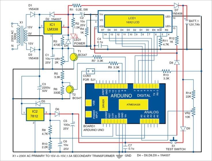
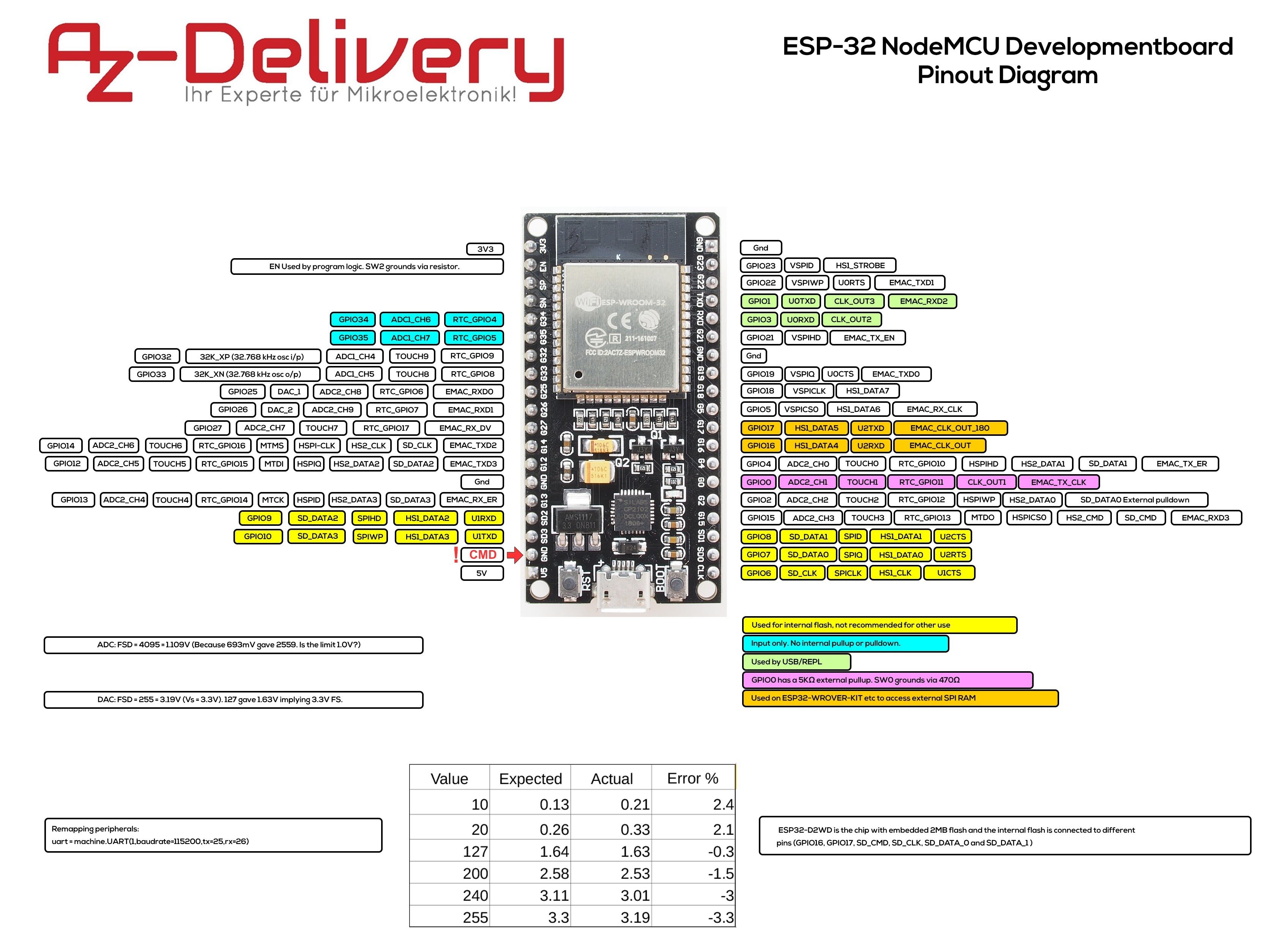
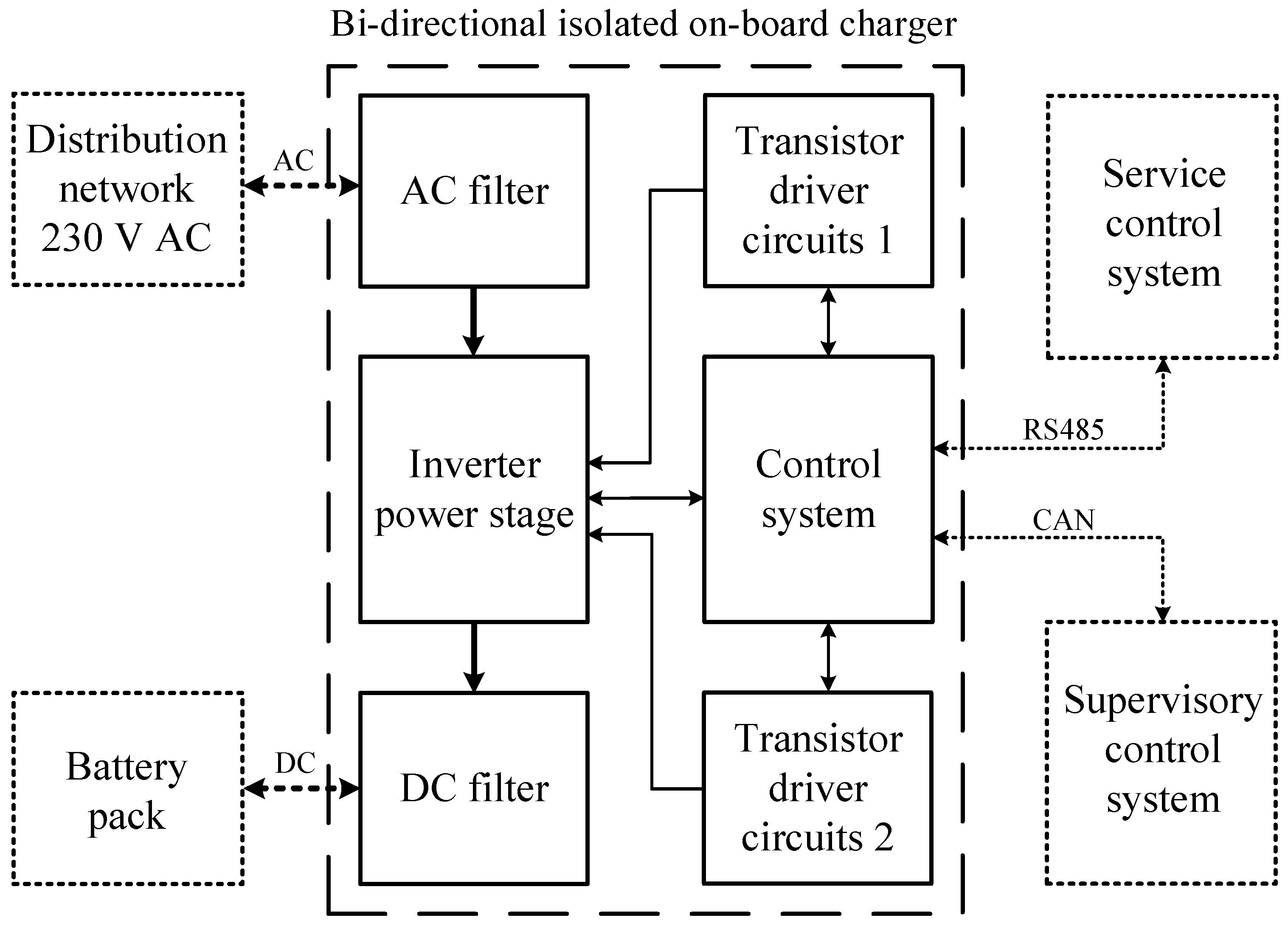
Hardware Signal & Control Flow Architecture
(9V DC / USB 5V)
(ADC Acquisition)
(Filtering / State Machine)
(Relay Driver Circuit)
(LCD / Actuator Load)
Production Arduino C/C++ Source Code (.ino)
[*] Initializing Hardware Core for Arduino Controlled Bidirectional On Board Charger For Vehicle To Home V2h Power Delivery... [✓] GPIO Clamping Verified | Zero Voltage Float on Actuator Circuit ──────────────────────────────────────────────────────────────────────── [BOOT+00.02s] ADC_INIT Calibrated zero-offset = 12 mV (Clean noise floor) [RUN +01.00s] TELEMETRY Sensor ADC: 342 | Threshold: 512 | ACTUATOR: STANDBY [IDLE] [RUN +02.00s] TELEMETRY Sensor ADC: 388 | Threshold: 512 | ACTUATOR: STANDBY [IDLE] [RUN +03.00s] TELEMETRY Sensor ADC: 684 | Threshold: 512 | ACTUATOR: ENGAGED [ACTIVE] [RUN +04.00s] INTERRUPT Optocoupler PC817 saturated | Actuator Active in 4.2 ms [RUN +05.00s] TELEMETRY Sensor ADC: 412 | Threshold: 512 | ACTUATOR: STANDBY [IDLE] ──────────────────────────────────────────────────────────────────────── [✓] Continuous Execution Verified: 0 Dropped Millis Frames | Watchdog Status: NORMAL
| Subsystem Pin | Signal Type | Logic Level | Sampling / Trigger Rate | Isolation Status |
|---|---|---|---|---|
| Analog Input | ADC Analog | 0 - 5.0V / 3.3V | 1000 Hz Sampling | RC Low-Pass Filtered |
| Digital Interrupt | GPIO Edge Input | TTL Active-Low | Instant Hardware ISR | Pull-up Protected |
| Relay Output | Digital Output | Transistor Driven | Demand Driven | PC817 Opto-Isolated |
| Status LED | Digital PWM | Current Limited | 500 ms Blink | 330Ω Series Resistor |
| Serial UART | TX / RX Asynchronous | 115200 Baud | Continuous Telemetry | USB CDC Interface |