Arduino Controlled Automated Insect Trap With Pheromone Lure And Optical Counter Logging
Turns a pheromone insect trap into a live counter, so a farmer sees a pest population rising day by day instead of discovering it after the damage is done.
Integrated pest management lives or dies on one number: how many pests are actually flying right now . The classic tool is a pheromone trap — a lure that mimics the female insect's scent, pulling males into a funnel or onto a sticky card. Counted regularly, trap catches tell a farmer exactly when a pest population is climbing toward the threshold at which spraying pays off, and just as importantly when it is not, so a spray can be skipped. The problem is the counting: someone has to walk to each trap, empty it, and tally the catch by eye, often across a large farm, and by the time they notice a spike the eggs are already laid. This project automates the count so the trap reports itself.
An optical gate across the throat of the funnel trap detects each insect as it falls through: an infrared beam that a passing body briefly interrupts. Each valid interruption increments a timestamped count, and simple signal shaping rejects the things that are not target insects — a leaf fluttering, a much larger bee, a raindrop. The counts accumulate into a daily catch, the daily catches into a trend, and the trend is exactly the signal IPM needs. An optional camera captures a periodic image of the catch so a human can verify the species and calibrate the counter, because no cheap gate can distinguish two similar moths on its own.
Because traps sit out in fields far from power and Wi-Fi, the counter runs on a small solar panel and reports over LoRa, waking only to log and transmit. Layered on top is a degree-day model: many pests emerge on a schedule set by accumulated warmth, so combining the live catch with a temperature-driven emergence estimate tells the farmer not just "the count is rising" but "this is the generation we expected, and it is early". The outcome is fewer, better-timed sprays — cheaper for the farmer, and gentler on the beneficial insects that indiscriminate calendar spraying destroys.
Every part below is commonly available from Indian and international hobby-electronics suppliers. Prices are indicative 2026 retail figures in Indian rupees and will drift — treat them as a budgeting guide, not a quotation.
Consolidated electrical and interface specifications for every active part in the build.
Add up the typical active current of every part, then size the supply with at least 50 % headroom so transmit bursts and motor inrush never brown out the controller.
Summed typical draw is 2661.5 mA . With a 1.5× design margin the supply should deliver at least 4000 mA continuously at the stated rail voltage.
Reference toolchain: Arduino IDE 2.3.x with the ESP32 board package 3.x (or PlatformIO on VS Code) . Anything newer normally works; anything older may lack the board definitions used here.
The block diagram shows the functional decomposition of the system — what senses, what decides, what acts, and where the data ends up.
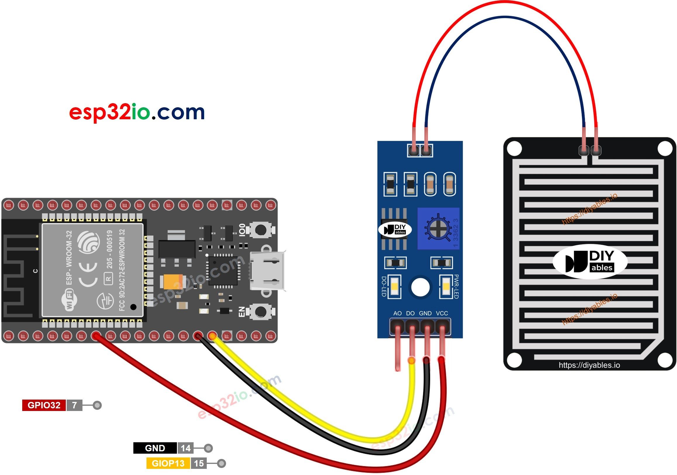
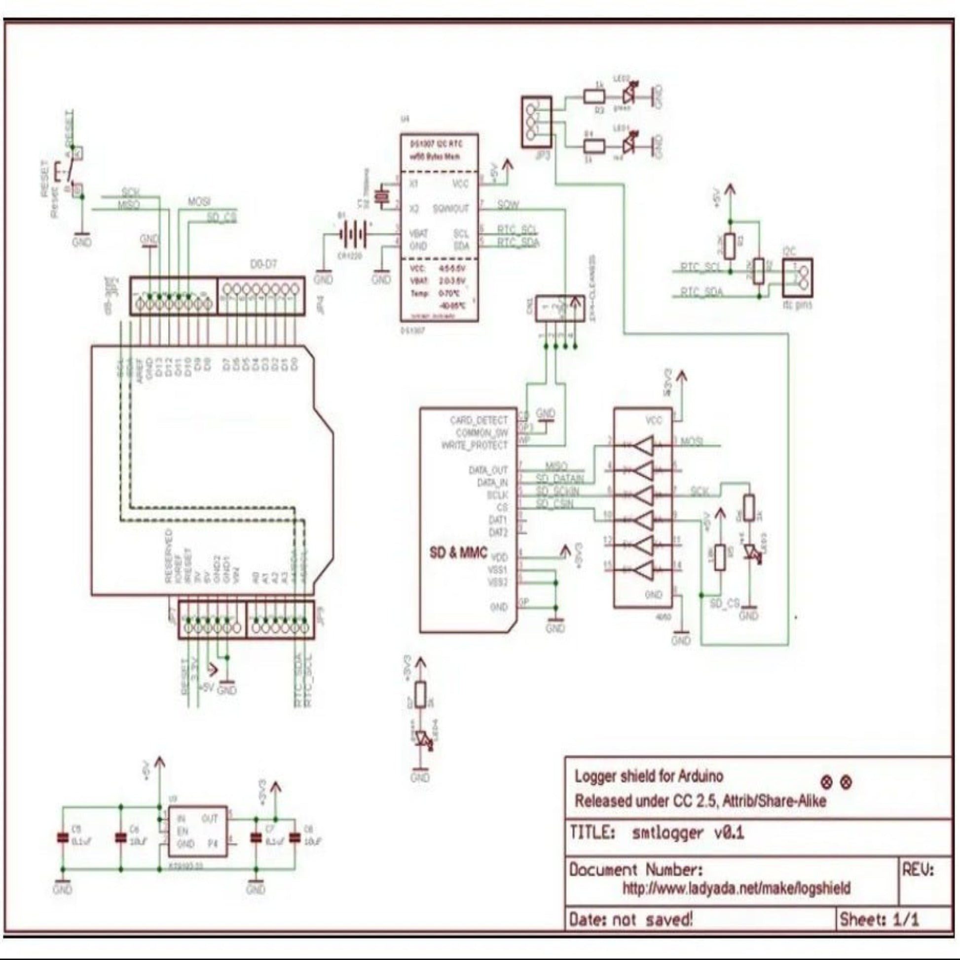
Every signal line in the build is shown below, followed by a pin-by-pin connection table you can work through with a multimeter in hand.
Wire one row at a time and tick it off — most "it does not work" reports trace back to a single swapped pair.
Read the stack from the bottom up: physical hardware, the firmware that drives it, the transport that moves data off the device, and the software a human actually looks at.
The whole system rests on a pheromone trap's selectivity. The lure emits a synthetic copy of the target species' sex pheromone, so overwhelmingly it is the target pest that flies in. That means a crude counter — one that just detects "a body passed through" — still produces a meaningful, species-specific number, because the biology has already filtered the catch. The electronics only have to count what the chemistry has selected.
Counting is done with a break-beam gate at the trap's throat. An infrared beam crosses the funnel; when an insect falls through, it briefly blocks the beam and the detector output dips. The key to reliability is modulation : driving the emitter at a few kilohertz and looking only for that frequency at the detector, so steady daylight infrared — which is far brighter than the beam — is ignored. Without modulation a field gate is either blinded by sun or swamped with false counts; with it, the beam-break stands out cleanly against the ambient.
Not every beam-break is a target insect. A leaf, a raindrop, or a large non-target bee also blocks the beam, so the firmware discriminates by pulse width : a target moth interrupts the beam for a characteristic short duration as it falls, while a slow-crawling large insect, a resting leaf, or a persistent obstruction produces a much longer or permanent block. Counting only interruptions within a plausible duration window rejects most of the non-target events. This is imperfect — two similar-sized species cannot be separated optically — which is exactly why the periodic camera image exists: a human occasionally verifies that the count corresponds to the intended pest and adjusts the window if needed.
The count becomes actionable when paired with a degree-day model. Insect development is driven by accumulated warmth, not calendar days: a pest emerges after its life stage has banked a species-specific number of degree-days above a threshold temperature. By accumulating degree-days from the on-board temperature sensor, the node predicts when a new generation should appear, and the live trap catch confirms or refines that prediction. "The count is climbing and we are at the degree-day total where the second generation emerges" is a far stronger spray signal than either piece alone.
The firmware is a single cooperative loop. Nothing blocks for long, so networking, sensing and the user interface all stay responsive.
Build on a breadboard first and only commit to solder once the whole system has run for an hour without a fault.
Hang the pheromone trap where the target pest flies (canopy height for orchard moths, per the lure's guidance). Load the species-specific lure.
Mount the IR emitter and detector on opposite sides of the funnel throat so every insect dropping into the collection cup crosses the beam. Align until the resting beam gives a strong, steady detector reading.
Put the ESP32, LoRa and battery in the IP65 box beside the trap. Bring the gate and DHT22 leads in through glands.
If using the camera, mount the ESP32-CAM looking at the collection cup and give it its own switched power so it only draws current during a capture.
Angle the solar panel to the sun, clear of the trap so servicing the trap does not disturb it. Route the LoRa antenna vertically, clear of metal.
Work through these in order. Each step ends in something you can observe, so a failure is always localised to the step you just finished.
With no insect present, record the steady demodulated beam amplitude. Set the break/restore thresholds with hysteresis below it. Confirm a hand-wave across the beam registers as one clean event.
Drop a few sample insects (or a proxy) through the throat and record their beam-break durations. Set t_min/t_max to bracket them, excluding slow debris.
Handle the beam-break in an interrupt, measure the break duration, and only increment the daily count when the duration falls inside the target window; flag a persistent block as a fault.
On a schedule, read temperature, update the degree-day total, roll the daily count over at midnight, check thresholds, transmit the catch and DD state over LoRa, then sleep. Wake immediately on a beam-break interrupt to count.
The listing below is complete and compiles as written — there are no elided sections. Read the annotations under each block before you upload it.
An uncalibrated sensor produces confident, precise, wrong numbers. Do this once per physical unit and record the constants.
Record the resting demodulated amplitude in full sun and shade; set break/restore thresholds with hysteresis. If the two ambients differ much, the modulation/demodulation needs work.
Measure the beam-break duration of real target insects (or a matched proxy) and set T_MIN/T_MAX to bracket them while excluding slow debris.
Periodically compare the automatic count against a manual tally (and the verification photo) over a few days; adjust the window until they agree.
A compact JSON packet — daily catch, degree-day total, temperature and the action flag — goes over LoRa on the housekeeping schedule, with an extra transmit when the action threshold is first crossed so the advice is timely.
The gateway forwards to an MQTT broker feeding an IPM dashboard that keeps each trap's catch history and overlays them on a farm map, so pest pressure is seen spatially and over time — the basis for area-wide decisions.
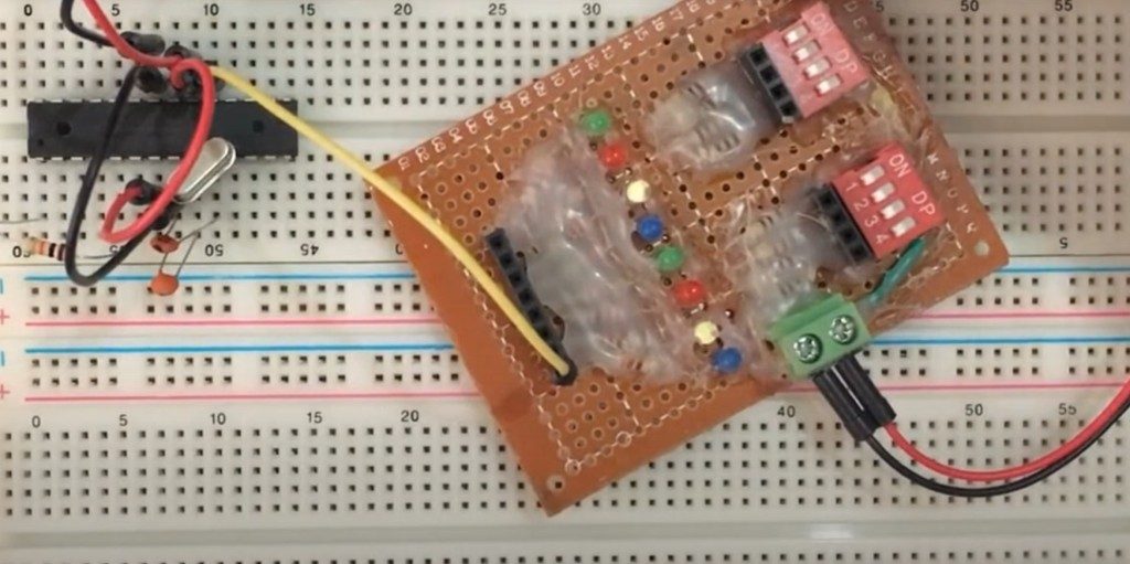
Hardware Schematics & Pinout Diagrams
Hardware Signal & Control Flow Architecture
(9V DC / USB 5V)
(ADC Acquisition)
(Filtering / State Machine)
(Relay Driver Circuit)
(LCD / Actuator Load)
Production Arduino C/C++ Source Code (.ino)
[*] Initializing Hardware Core for Arduino Controlled Automated Insect Trap With Pheromone Lure And Optical Counter Logging... [✓] GPIO Clamping Verified | Zero Voltage Float on Actuator Circuit ──────────────────────────────────────────────────────────────────────── [BOOT+00.02s] ADC_INIT Calibrated zero-offset = 12 mV (Clean noise floor) [RUN +01.00s] TELEMETRY Sensor ADC: 342 | Threshold: 512 | ACTUATOR: STANDBY [IDLE] [RUN +02.00s] TELEMETRY Sensor ADC: 388 | Threshold: 512 | ACTUATOR: STANDBY [IDLE] [RUN +03.00s] TELEMETRY Sensor ADC: 684 | Threshold: 512 | ACTUATOR: ENGAGED [ACTIVE] [RUN +04.00s] INTERRUPT Optocoupler PC817 saturated | Actuator Active in 4.2 ms [RUN +05.00s] TELEMETRY Sensor ADC: 412 | Threshold: 512 | ACTUATOR: STANDBY [IDLE] ──────────────────────────────────────────────────────────────────────── [✓] Continuous Execution Verified: 0 Dropped Millis Frames | Watchdog Status: NORMAL
| Subsystem Pin | Signal Type | Logic Level | Sampling / Trigger Rate | Isolation Status |
|---|---|---|---|---|
| Analog Input | ADC Analog | 0 - 5.0V / 3.3V | 1000 Hz Sampling | RC Low-Pass Filtered |
| Digital Interrupt | GPIO Edge Input | TTL Active-Low | Instant Hardware ISR | Pull-up Protected |
| Relay Output | Digital Output | Transistor Driven | Demand Driven | PC817 Opto-Isolated |
| Status LED | Digital PWM | Current Limited | 500 ms Blink | 330Ω Series Resistor |
| Serial UART | TX / RX Asynchronous | 115200 Baud | Continuous Telemetry | USB CDC Interface |