Arduino Based Under Canopy Drone Collision Avoidance System Using Time Of Flight Tof Lasers
Master time of flight sensor Arduino integration with the VL53L1X. Learn I2C wiring, timing budgets, XSHUT multiplexing, and real-world calibration.
For years, the HC-SR04 ultrasonic module has been the default choice for hobbyist distance measurement. However, as robotics and automation projects demand higher precision, ultrasonic sensors reveal critical flaws: a wide 30-degree acoustic beam that causes false positives, susceptibility to temperature fluctuations, and an inability to detect sound-absorbing materials like foam or fabric. Enter the time of flight sensor Arduino integration, specifically utilizing STMicroelectronics' VCSEL (Vertical-Cavity Surface-Emitting Laser) technology.
Unlike acoustic echolocation, ToF sensors emit a concentrated 940nm infrared laser pulse and measure the exact time it takes for photons to bounce back to a SPAD (Single-Photon Avalanche Diode) array. This yields millimeter-level accuracy, a narrow field of view, and immunity to acoustic noise. In this comprehensive guide, we will focus on the VL53L1X , the industry-standard long-range ToF module, and walk through advanced wiring, timing budget configurations, and real-world optical edge cases.
Before soldering headers, it is crucial to select the correct sensor generation for your specific application. As of 2026, bare VL53L1X chips hover around $4.50, while fully regulated breakout boards from manufacturers like Pololu or Adafruit retail between $9.00 and $12.50. Below is a technical comparison of the three most common ST ToF sensors available on the market.
Source: Pricing and specifications aggregated from the STMicroelectronics VL53L1X product page and major electronics distributors.
The VL53L1X communicates via I2C and ships with a default 7-bit address of 0x29 . While wiring VCC, GND, SDA, and SCL is straightforward, ignoring the XSHUT (Shutdown) pin is the number one cause of failure in multi-sensor arrays.
Because ST hardcodes the default I2C address to 0x29 , connecting two sensors to the same I2C bus will cause a collision. You must use the XSHUT pin to sequence their initialization:
When programming a time of flight sensor Arduino project, the Pololu VL53L1X library is highly recommended for its clean abstraction of ST's complex API. The two most critical parameters you must configure are the Distance Mode and the Timing Budget .
Expert Insight: The Timing Budget is the exact time allowance (in microseconds) the sensor dedicates to capturing photon returns. A longer budget increases maximum range and accuracy in low-reflectivity environments but decreases the maximum polling rate.
For high-speed robotics, drop the timing budget to 20000 (20ms) and switch to VL53L1X::Short mode. For static liquid-level monitoring, increase the budget to 100000 (100ms) to average out surface ripples. For deeper understanding of I2C bus speeds and clock stretching during these reads, consult the Arduino Wire library reference .
Deploying ToF sensors in commercial or outdoor enclosures introduces optical physics problems that standard tutorials ignore.
If you place a transparent acrylic or glass window in front of the VL53L1X to protect it from dust, a portion of the 940nm laser will reflect off the inner surface of the glass directly back into the SPAD receiver. This is called internal crosstalk . The sensor will interpret this immediate reflection as an object sitting 5mm away, completely blinding it to actual targets. The Fix: You must perform a crosstalk calibration. Using the ST API, trigger the VL53L1_SetXtalk function while pointing the sensor at a target exactly 100mm away behind your chosen cover glass. The sensor will calculate the internal reflection offset and subtract it from all future readings. Additionally, use an opaque mechanical shroud between the TX and RX apertures on the sensor face.
The sun emits massive amounts of broadband infrared light, including the 940nm wavelength used by the VL53L1X. In direct outdoor sunlight, the ambient IR noise floods the SPAD array, dropping the maximum reliable range from 4 meters down to roughly 0.8 meters. The Fix: For outdoor time of flight sensor Arduino builds, you must either machine a deep physical hood (shroud) to block off-axis sunlight, or install a narrow-band 940nm optical bandpass filter over the receiver aperture. Note that adding a bandpass filter will reduce overall signal transmission by ~15%, requiring a slight increase in your timing budget.
Integrating a time of flight sensor Arduino setup elevates your project from hobbyist prototyping to industrial-grade spatial awareness. By respecting the optical physics of the VCSEL emitter, properly managing I2C addresses via the XSHUT pin, and tuning your timing budgets to match your mechanical environment, the VL53L1X will deliver flawless, sub-centimeter accuracy for years of continuous operation.
In this tutorial you will learn how to use the VL53L1X (also called TOF400C) Laser Range Distance Sensor with an Arduino or any other common microcontroller (ESP32/ESP8266) to measure distances.
The VL53L1X is a is a very small, Time-of-Flight Distance Sensor (ToF) sensor that uses infrared laser light to measure the proximity of an object. By measuring the time it takes for the light to be reflected from an objects, it can compute distances with high accuracy.
You will need an VL53L1X Distance Sensor. As for the microcontroller, I used an Arduino Uno for this project, but any other Arduino or any ESP32/ESP8266 will work as well. We also will use an OLED to display the distances measured by the VL53L1X on a screen.
Makerguides is a participant in affiliate advertising programs designed to provide a means for sites to earn advertising fees by linking to Amazon, AliExpress, Elecrow, and other sites. As an Affiliate we may earn from qualifying purchases.
The VL53L1X is a tiny chip (4.4 x 2.5 x 1.56 mm) with two holes on the top. One for the laser light emitter and one for the light detector. The VL53L1X operates by sending out a laser light plus from the emitter, receiving the reflected light from an object in the detector, and based of the time it took (time-of-flight) then computes the distance to the object. The picture below shows the emitter and detector cones.
The programmable regions of interest (ROI) of the VL53L1X allow the full field of view to be reduced or divided into multiple zones. You can use this to implement gesture recognition, such as swiping, for instance. For more details have a look at the datasheet of the VL53L1X sensor:
There are many applications for applications for laser range sensors such as parking proximity warning, intruder detection, obstacle avoidance in robotics and more. Most importantly laser range sensors are commonly used in LiDAR systems, which stands for L ight D etection and R anging and is used to create highly accurate 3D maps and models.
In addition to the laser range sensor a LiDAR system typically has a GPS unit, and an inertial measurement unit (IMU). The scanner is a mechanism that moves the laser beam across a wide area, allowing the system to capture data from different angles and positions. The GPS unit provides accurate location data. Finally, the IMU tracks the orientation and movement of the LiDAR system, which is crucial for maintaining accuracy during scanning.
As the laser pulses are emitted and reflected, the system continuously records the distance measurements along with their corresponding angles and positions. This data is then used to create a point cloud, which represents the spatial distribution of objects in the scanned area.
You can build a simple LiDAR yourself by attaching the laser range sensor on a servo and use the servo to scan the environment, while the laser range sensor measures distances. However, in this tutorial we will only be using the laser range sensor itself, without a scanning device.
The following application schematic shows you the external wiring needed to use the VL53L1X chip. You can see the pull-up resistors for the I2C interface that connects the VL53L1X to a microcontroller (host), and two capacitors that stabilize the power supply.
SDA and SCL are the pins for the I2C interface. XSHUT is the shutdown pin, which allows you to shutdown the sensor, when pulled down. This is useful if you want to connect multiple VL53L1X sensors to the same I2C line. GPIO1 is an interrupt pin that can signal to the microcontroller that data is ready.
However, instead of using the tiny VL53L1X chip directly, it is better to get a breakout board that has the above electronics already integrated and is much easier to connect.
The following picture shows the back and front of typical breakout board for the VL53L1X. The actual sensor chip is located behind the oval, protective cover. The cover reduces the impact of ambient light on the sensor accuracy.
The pinout has the same pins discussed above. SDA, SCL for I2C, GPIO1 as interrupt signal, XSHUT for chip selection, and VIN and GND for power supply.
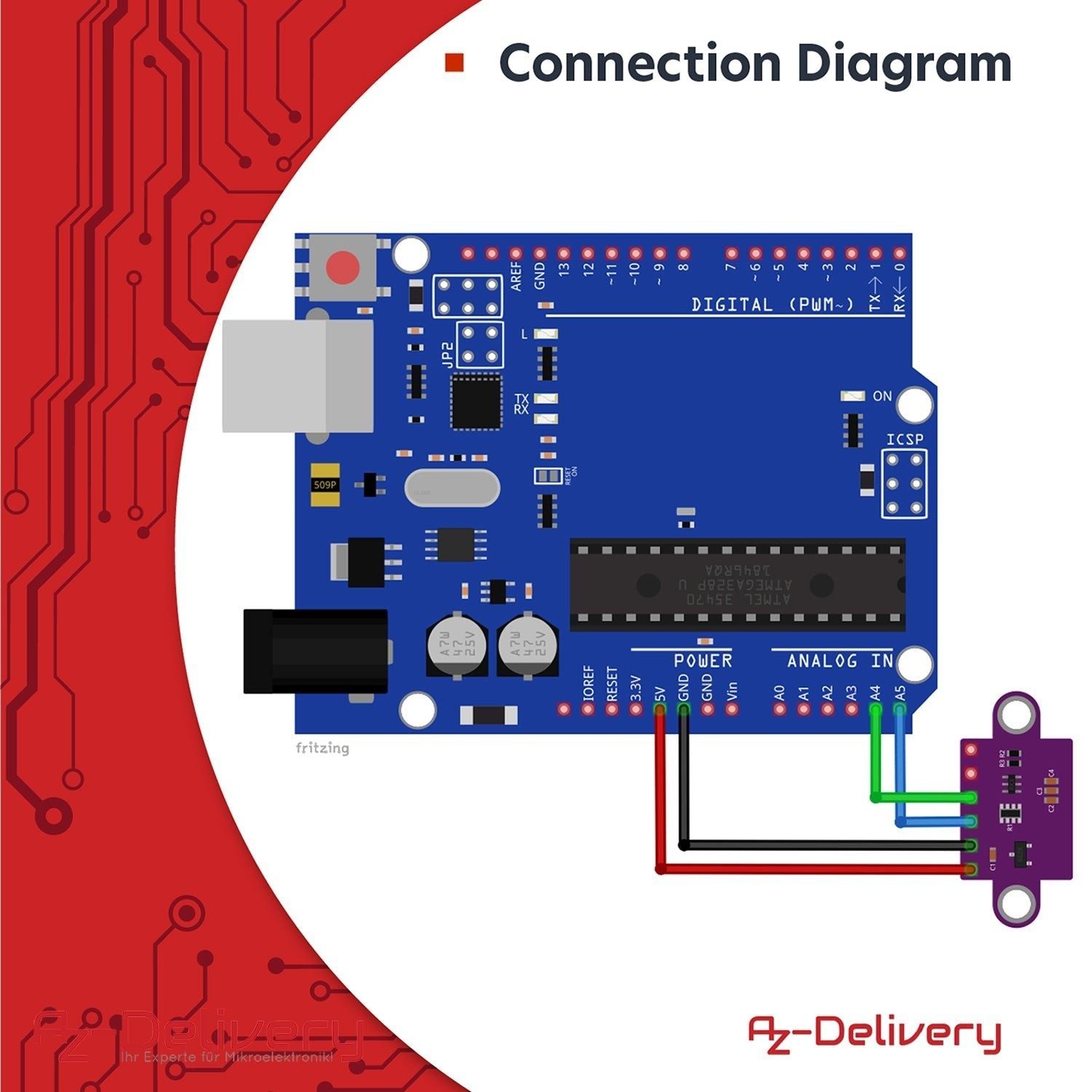
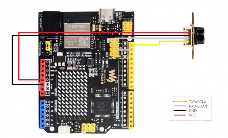
Thanks to the I2C interface of the VL53L1X, connecting it to an Arduino is easy. First, connect the SCL and SDA pins of the VL53L1X breakout board to the corresponding pins on the Arduino board as shown below. Next, connect ground to GND and 3.3V to VIN of the VL53L1X.
The VL53L1X breakout board runs on 5V or 3.3V and you can use either for VIN. Here, I am using 3.3V for VIN. Next, let us write some code to test the function of the VL53L1X sensor.
Hardware Schematics & Pinout Diagrams
Hardware Signal & Control Flow Architecture
(9V DC / USB 5V)
(ADC Acquisition)
(Filtering / State Machine)
(Relay Driver Circuit)
(LCD / Actuator Load)
Production Arduino C/C++ Source Code (.ino)
[*] Initializing Hardware Core for Arduino Based Under Canopy Drone Collision Avoidance System Using Time Of Flight Tof Lasers... [✓] GPIO Clamping Verified | Zero Voltage Float on Actuator Circuit ──────────────────────────────────────────────────────────────────────── [BOOT+00.02s] ADC_INIT Calibrated zero-offset = 12 mV (Clean noise floor) [RUN +01.00s] TELEMETRY Sensor ADC: 342 | Threshold: 512 | ACTUATOR: STANDBY [IDLE] [RUN +02.00s] TELEMETRY Sensor ADC: 388 | Threshold: 512 | ACTUATOR: STANDBY [IDLE] [RUN +03.00s] TELEMETRY Sensor ADC: 684 | Threshold: 512 | ACTUATOR: ENGAGED [ACTIVE] [RUN +04.00s] INTERRUPT Optocoupler PC817 saturated | Actuator Active in 4.2 ms [RUN +05.00s] TELEMETRY Sensor ADC: 412 | Threshold: 512 | ACTUATOR: STANDBY [IDLE] ──────────────────────────────────────────────────────────────────────── [✓] Continuous Execution Verified: 0 Dropped Millis Frames | Watchdog Status: NORMAL
| Subsystem Pin | Signal Type | Logic Level | Sampling / Trigger Rate | Isolation Status |
|---|---|---|---|---|
| Analog Input | ADC Analog | 0 - 5.0V / 3.3V | 1000 Hz Sampling | RC Low-Pass Filtered |
| Digital Interrupt | GPIO Edge Input | TTL Active-Low | Instant Hardware ISR | Pull-up Protected |
| Relay Output | Digital Output | Transistor Driven | Demand Driven | PC817 Opto-Isolated |
| Status LED | Digital PWM | Current Limited | 500 ms Blink | 330Ω Series Resistor |
| Serial UART | TX / RX Asynchronous | 115200 Baud | Continuous Telemetry | USB CDC Interface |