Arduino Based Multi Depth Soil Temperature And Moisture Profiler For Precision Vineyards
Whether you're a beginner learning how to connect a soil moisture sensor with Arduino or building advanced automatic plant watering systems , this step-by-step tutorial covers everything you need. We'll show you the exact Arduino soil moisture sensor wiring diagram , provide working Arduino soil moisture sensor code , and guide you through common troubleshooting scenarios that every maker encounters.
Update: This article was updated in June 2025 with more troubleshooting features, and the Arduino soil moisture sensor programming code was also tested to work with the latest Arduino UNO R4 Wifi Development board.
The Soil moisture sensor Arduino, a.k.a the soil humidity sensor, has four pins: VCC, GND, Aout, Dout. These four pins can be used to get the soil moisture data from the sensor, The pinout of the Soil Moisture Sensor is as follows:
VCC is the power supply pin of the soil moisture sensor that can be connected to 3.3V or 5V of the supply. But do note that the analog output will vary depending on the provided supply voltage.
GND is the ground pin of the board, and it should be connected to the ground pin of the Arduino
DOUT is the Digital output pin of the board; output low indicates soil moisture is appropriate, and high indicates soil moisture is low.
AOUT is the Analog output pin of the board that will give us an analog signal between VCC+ and ground for your soil moisture sensor Arduino project.
The working of the soil humidity sensor is pretty simple and straightforward, as you can see in the image below. We just need to stick the fork-shaped conductive probe to the soil, as the probe has two exposed conductive plates that will act as a variable resistor whose resistance will vary depending on the water content in the soil. Understanding the Arduino soil moisture sensor working principle is crucial for successful implementation in your projects.
This resistance of the probe is inversely proportional to the soil moisture of the device. The more water in the soil, the better the conductivity, which will result in lower resistance. The less water in the soil, the poorer the conductivity, which means higher resistance. This Arduino moisture sensor produces an output voltage according to the resistance by measuring which we can determine the moisture level.
The above GIF working of the Soil Moisture sensor shows how the analog output of sensor changes based on the water level in the soil. As you can see, the voltage drops from 5V to 0V when water is added to the soil. You can also see that the signal LED on the board turns on when water is added to the soil. We have not shown how the digital pin works in the above GIF to keep things simple. When water is added to the soil, the digital pin moves from low (0V) to high (5V) with the help of a board comparator op-amp. You can control the sensitivity of this digital pin using the potentiometer (blue) on the module. The sensor's analog output voltage varies inversely with soil moisture content, making it perfect for Arduino soil moisture sensor programming applications.
The entire soil humidity sensor consists of two parts: the first one is the soil moisture sensor probe, and the second one is an electronic module. The module processes the incoming data from the probe and which is processed by a microcontroller like Arduino, and we get the final output. The complete soil moisture sensor Arduino system consists of two main components working together:
As we have said earlier, the sensor contains a fork-shaped probe with two big exposed conductive pads. The probe acts like a variable potentiometer, the value of which can be read by a microcontroller like Arduino.
The soil moisture sensor module is there to convert the incoming analog signal to a digital signal; this is designed in such a way that the sensor can be used without microcontroller support. The module consists of two signal input pins where the probe gets connected. It also has four other pins, two of which are VCC and GND. The other two are Digital Output and Analog Output pins.
This module also consists of a High Precision Comparator, LM393, that is used to digitise the analog signal coming out of the sensor probe. The module has a built-in potentiometer that is used for sensitivity adjustment of the digital output. The main objective of the potentiometer is to set a threshold, so that when the moisture level exceeds the threshold value, the module will output LOW, otherwise HIGH. This feature of the module can come in very handy because when a certain threshold is reached, you can trigger a relay that can start pumping water.
Sensors should be placed at several different depths and locations in the field. Typically, sensors are placed in pairs at one-third and two-thirds the depth of the crop root zone and at two or more locations in the field, preferably away from high points, depressions and slopes.
When you purchase a soil moisture sensor module, it comes in two parts: the sensing probe and the module with a few components. To fully understand how the sensor module works, we have to look at the circuit of the module. The schematic diagram for the soil moisture sensor module is shown below. The schematic itself is very simple and needs a handful of generic components to build. If you don't have a prebuilt module on hand but still want to test your project, the schematic below will come in handy.
In the schematic, we have an LM393 op-amp, which is a low-power, low offset voltage op-amp that can be powered from a 3.3V or 5V supply. Please note that the analog output voltage of the device will depend on the input voltage. The main job for this op-amp is to convert the incoming analog signal from the sensor probe to a digital signal. There is also this 10K potentiometer that is used to set a reference voltage for the op-amp. The input voltage of the sensor goes below the threshold voltage set by the potentiometer, the output of the op-map goes low. Other than that, we have two LEDs. The first one is a power LED, and the other one is the trigger LED. The power LED turns on when power is applied to the board, and the trigger LED turns on when a certain set threshold is reached. This is how this basic circuit works.
Before testing it on a live circuit, let’s simulate it on Thinker CAD. Here is the Thinkercad simulation for the Arduino Soil moisture sensor.
Click on the start simulation button to test the circuit. You can adjust the sensor value by adjusting the slider that appears when clicking on the sensor. The Tinkercad code for Arduino Soil moisture sensor will show the humidity level using the 5 LEDs connected to Arduino. If you want to edit the code, please click on the code button and modify it as you need.
Now that we have a complete understanding of how a Soil Moisture sensor works, we can connect all the required wires to the Arduino UNO board. This section of the article will be divided into two parts, one showing analog output and the one showing the digital output. Let's begin with analog circuitry. The complete circuit to connect a soil humidity sensor with Arduino is shown below. For Arduino soil moisture sensor analog readings, use this proven wiring configuration:
To work with the sensor, we need to power the sensor first; for that, we are using the 5V and GND pins of the Arduino UNO Board. The soil moisture sensor Arduino circuit diagram shows the internal workings:
As shown in the above Arduino soil moisture sensor circuit diagram, we have connected an LED to digital PIN 6 of the Arduino and the analog out pin of the sensor is connected to the A0 pin of the Arduino UNO board. Finally, the ground is common between the LED and the sensor. We will program the Arduino so that the brightness of the LED will change depending on the soil moisture data sensed by the probe.
For the digital interface part, we are also using the +5V and Ground from the Arduino to power the sensor module.
Connecting a soil moisture sensor to an Arduino or any other microcontroller is pretty simple. As we all know, the sensor outputs both analog and digital signals, so processing this signal is very easy.
Quick Connection Verification: Before uploading code, verify your connections by checking:
Once your Arduino soil moisture sensor connections are complete, you're ready to upload the code and start monitoring soil moisture levels. The next section covers the complete circuit diagrams with visual references.
The code for the Arduino-based soil moisture sensor is very simple and easy to understand. We are just reading the analog data out of the sensor and changing the brightness of the LED according to the received data. Please do remember that we are only processing the analog data coming out of the sensor; for the digital data, you can see the onboard LED in the module light up.
Hardware Schematics & Pinout Diagrams
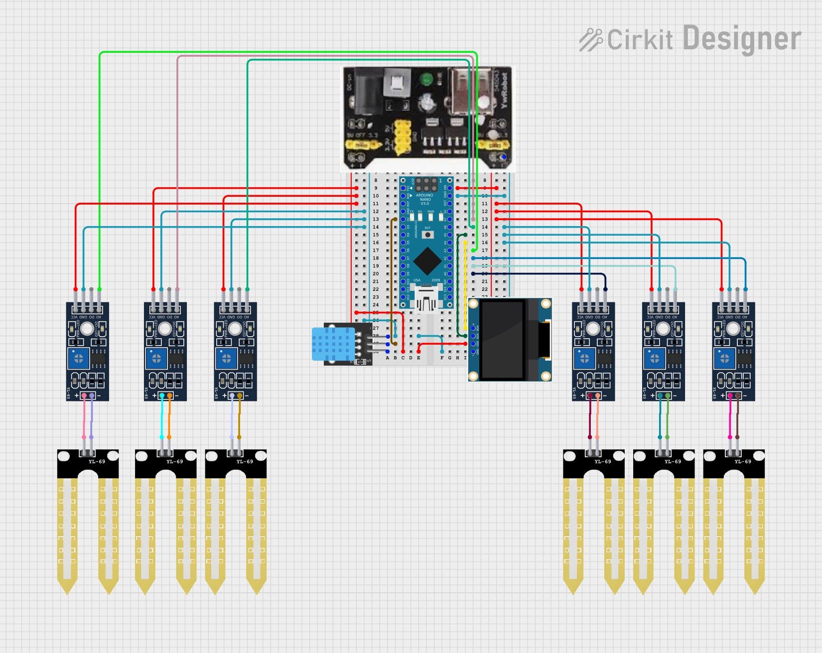
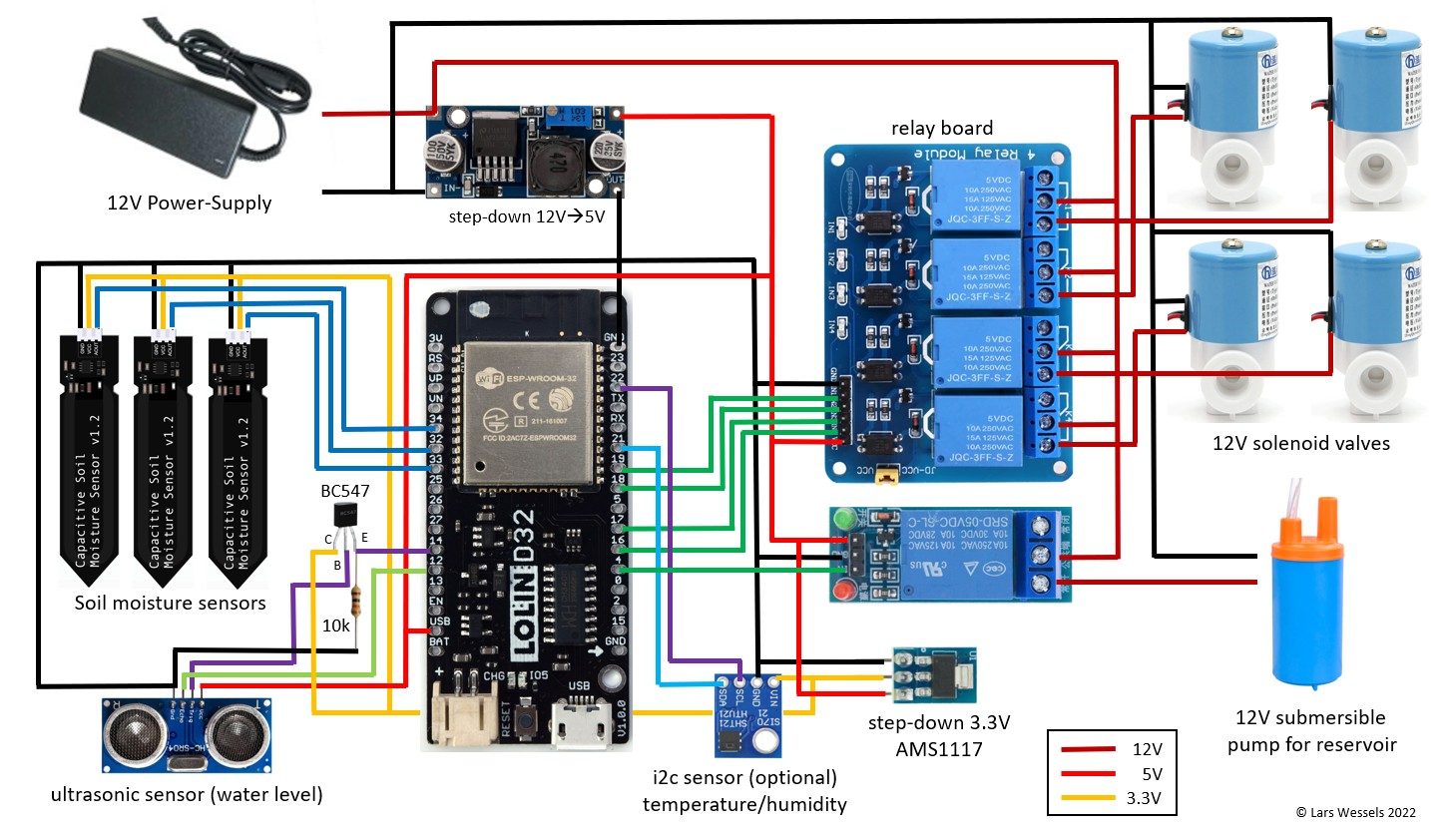
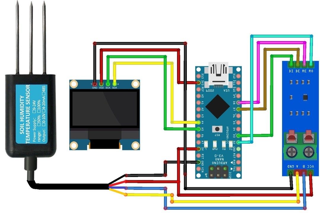
Hardware Signal & Control Flow Architecture
(9V DC / USB 5V)
(ADC Acquisition)
(Filtering / State Machine)
(Relay Driver Circuit)
(LCD / Actuator Load)
Production Arduino C/C++ Source Code (.ino)
[*] Initializing Hardware Core for Arduino Based Multi Depth Soil Temperature And Moisture Profiler For Precision Vineyards... [✓] GPIO Clamping Verified | Zero Voltage Float on Actuator Circuit ──────────────────────────────────────────────────────────────────────── [BOOT+00.02s] ADC_INIT Calibrated zero-offset = 12 mV (Clean noise floor) [RUN +01.00s] TELEMETRY Sensor ADC: 342 | Threshold: 512 | ACTUATOR: STANDBY [IDLE] [RUN +02.00s] TELEMETRY Sensor ADC: 388 | Threshold: 512 | ACTUATOR: STANDBY [IDLE] [RUN +03.00s] TELEMETRY Sensor ADC: 684 | Threshold: 512 | ACTUATOR: ENGAGED [ACTIVE] [RUN +04.00s] INTERRUPT Optocoupler PC817 saturated | Actuator Active in 4.2 ms [RUN +05.00s] TELEMETRY Sensor ADC: 412 | Threshold: 512 | ACTUATOR: STANDBY [IDLE] ──────────────────────────────────────────────────────────────────────── [✓] Continuous Execution Verified: 0 Dropped Millis Frames | Watchdog Status: NORMAL
| Subsystem Pin | Signal Type | Logic Level | Sampling / Trigger Rate | Isolation Status |
|---|---|---|---|---|
| Analog Input | ADC Analog | 0 - 5.0V / 3.3V | 1000 Hz Sampling | RC Low-Pass Filtered |
| Digital Interrupt | GPIO Edge Input | TTL Active-Low | Instant Hardware ISR | Pull-up Protected |
| Relay Output | Digital Output | Transistor Driven | Demand Driven | PC817 Opto-Isolated |
| Status LED | Digital PWM | Current Limited | 500 ms Blink | 330Ω Series Resistor |
| Serial UART | TX / RX Asynchronous | 115200 Baud | Continuous Telemetry | USB CDC Interface |