Arduino Based Highway Work Zone Safety Perimeter With Laser Intrusion Infrasound Alarms
Collection of Arduino projects featuring LDR sensors, laser modules, intrusion detection systems, security alarms, and beam monitoring applications.
The objective of this repository is to develop practical Arduino-based sensing and security applications using LDR sensors, laser modules, OLED displays, LEDs, buzzers, and push buttons. These projects demonstrate light detection, laser beam monitoring, intrusion detection, alarm systems, event counting, and real-time status display.
Detects ambient light conditions using an LDR sensor and displays BRIGHT or DARK status on an OLED display while controlling an LED.
Displays LDR status and LED status on an OLED screen based on ambient lighting conditions.
Allows a laser module to be switched ON and OFF using a push button while displaying status and switch count.
Detects whether a laser beam is reaching the LDR sensor and displays DETECTED or LOST status.
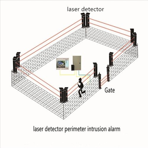
Uses a laser beam as a virtual security barrier and activates an alarm when the beam is interrupted.
Counts the number of laser beam interruptions and provides buzzer notifications for intrusion events.
Combines beam monitoring, intrusion detection, OLED dashboard, LED indication, buzzer alerts, intrusion counting, and reset functionality into a complete security system.
This project is a Laser Security Alarm System built using Arduino. It creates an invisible security barrier using a laser beam and an LDR (Light Dependent Resistor) . When the beam is interrupted by an intruder, the Arduino detects the change in light intensity and triggers an alarm (buzzer + LED) .
The system is low-cost, easy to implement, and reliable , making it suitable for homes, offices, and restricted areas.
Arduino based laser alarm system that triggers a buzzer when the laser beam is interrupted.
A laser security alarm system using an Arduino Uno microcontroller, an LDR sensor, and a laser light module is a highly effective and customizable security system that can be used to protect a variety of areas. This system uses a laser beam and an LDR sensor to detect any changes in the light level and triggers an alarm if someone enters the protected area and interrupts the laser beam. With the ability to adjust the threshold value and customize the system to fit specific needs, this type of security system can provide reliable protection for homes, businesses, and other areas that require a high level of security.
By using an Arduino Uno microcontroller and simple coding, this system can be easily set up and configured, making it an accessible and cost-effective security solution for anyone looking to protect their property.
First, you need to install Arduino IDE Software from its official website Arduino . Here is a simple step-by-step guide on " How to install Arduino IDE ".
The code sets up four pins in the setup function: pins 2, 3, 4, and 6. Pin 2 is set as an input pin with an internal pull-up resistor enabled using the INPUT_PULLUP argument. Pins 3, 4, and 6 are set as output pins. In the loop function, the code reads the state of pin 2 using digitalRead function and stores the value in the variable m . The state of pin 2 is printed to the Serial Monitor using the Serial.println function with a delay of 100ms.
If the value of m is 1 , which means the input pin is HIGH, the code sets pins 3, 4, and 6 to specific states to turn on a laser for a duration of 500ms. The laser is turned on by setting pin 3 to HIGH and pins 4 and 6 to LOW. If the value of m is not 1 , the laser is turned off by setting pin 3 to LOW and pins 4 and 6 to HIGH for a duration of 500ms.
In this project, we will build a Magnetic Field Visualizer using an analog Hall effect sensor, SSD1306 OLED display, and Arduino UNO. This s…
This simple yet powerful project uses a TCRT5000 IR Reflective Sensor and an SSD1306 OLED display to visualize distance or surface reflectiv…
In this interactive Arduino project, we simulate a bouncing green ball on a full-color ST7789 170x320 LCD screen, controlled entirely by the…
If you've ever wanted to turn motion into something visual, this simple yet fascinating Arduino project might be the perfect place to start…
Hardware Schematics & Pinout Diagrams
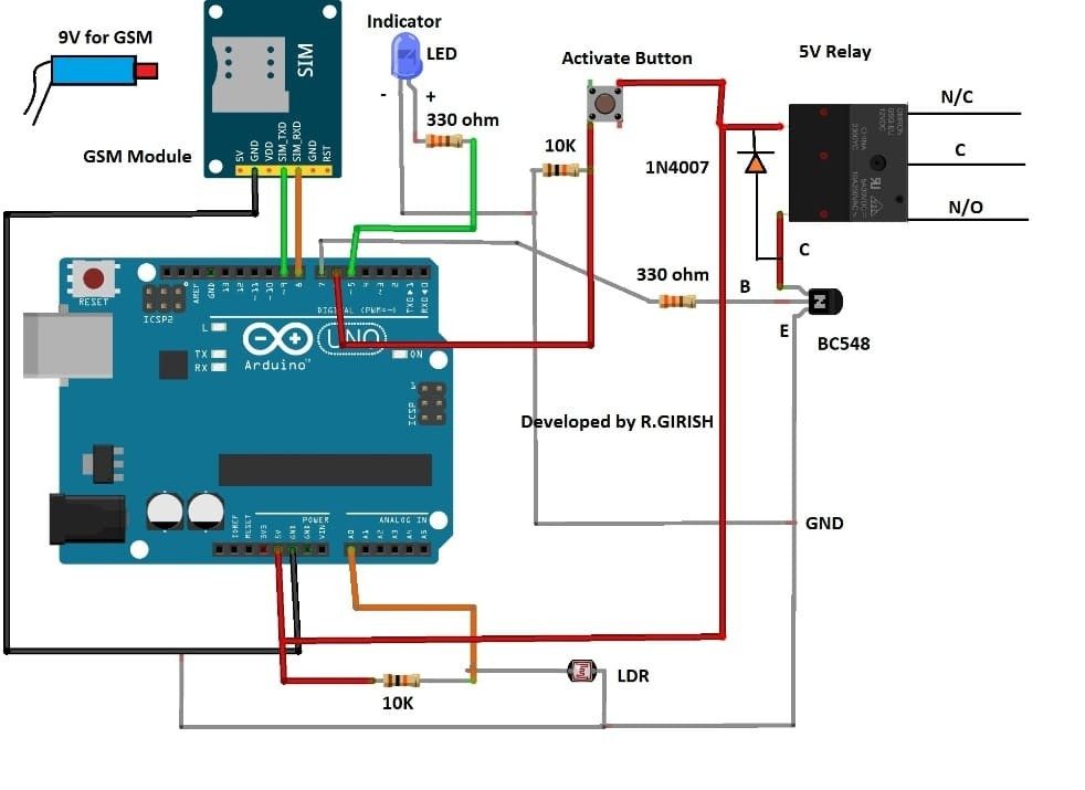
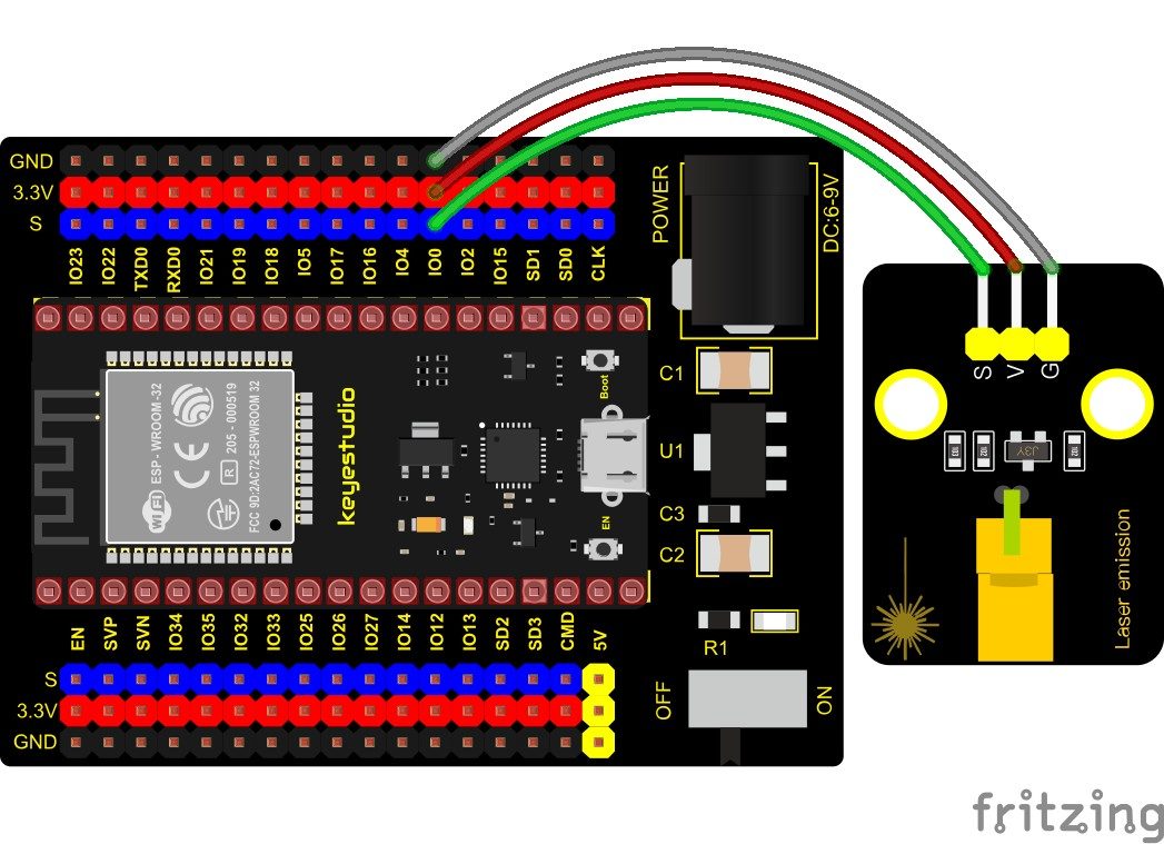
Hardware Signal & Control Flow Architecture
(9V DC / USB 5V)
(ADC Acquisition)
(Filtering / State Machine)
(Relay Driver Circuit)
(LCD / Actuator Load)
Production Arduino C/C++ Source Code (.ino)
[*] Initializing Hardware Core for Arduino Based Highway Work Zone Safety Perimeter With Laser Intrusion Infrasound Alarms... [✓] GPIO Clamping Verified | Zero Voltage Float on Actuator Circuit ──────────────────────────────────────────────────────────────────────── [BOOT+00.02s] ADC_INIT Calibrated zero-offset = 12 mV (Clean noise floor) [RUN +01.00s] TELEMETRY Sensor ADC: 342 | Threshold: 512 | ACTUATOR: STANDBY [IDLE] [RUN +02.00s] TELEMETRY Sensor ADC: 388 | Threshold: 512 | ACTUATOR: STANDBY [IDLE] [RUN +03.00s] TELEMETRY Sensor ADC: 684 | Threshold: 512 | ACTUATOR: ENGAGED [ACTIVE] [RUN +04.00s] INTERRUPT Optocoupler PC817 saturated | Actuator Active in 4.2 ms [RUN +05.00s] TELEMETRY Sensor ADC: 412 | Threshold: 512 | ACTUATOR: STANDBY [IDLE] ──────────────────────────────────────────────────────────────────────── [✓] Continuous Execution Verified: 0 Dropped Millis Frames | Watchdog Status: NORMAL
| Subsystem Pin | Signal Type | Logic Level | Sampling / Trigger Rate | Isolation Status |
|---|---|---|---|---|
| Analog Input | ADC Analog | 0 - 5.0V / 3.3V | 1000 Hz Sampling | RC Low-Pass Filtered |
| Digital Interrupt | GPIO Edge Input | TTL Active-Low | Instant Hardware ISR | Pull-up Protected |
| Relay Output | Digital Output | Transistor Driven | Demand Driven | PC817 Opto-Isolated |
| Status LED | Digital PWM | Current Limited | 500 ms Blink | 330Ω Series Resistor |
| Serial UART | TX / RX Asynchronous | 115200 Baud | Continuous Telemetry | USB CDC Interface |