Arduino Based Hailstorm Kinetic Impact Force Energy Counter Using Piezoelectric Discs
Learn how to configure an Arduino piezoelectric sensor circuit. This guide covers voltage clamping, charge amplification, and ADC threshold tuning.
Configuring an arduino piezoelectric sensor requires a fundamental understanding of the direct piezoelectric effect. When mechanical stress is applied to a piezoceramic material (typically Lead Zirconate Titanate, or PZT), it generates an electrical charge. Unlike standard resistive or capacitive sensors, a piezoelectric disc behaves electrically as a high-impedance voltage source in parallel with an internal capacitor. For a standard 27mm brass-mounted PZT disc, such as the Murata 7BB-27-4L0, the internal capacitance is approximately 20nF. While this setup is excellent for detecting knocks, vibrations, and acoustic emissions, connecting it directly to an Arduino's analog-to-digital converter (ADC) is a recipe for hardware failure and erratic data.
This configuration guide details the exact hardware conditioning, charge amplification, and software thresholding required to reliably interface piezoelectric elements with the ATmega328P and similar microcontrollers in 2026.
A common beginner mistake is wiring one leg of the piezo disc to ground and the other to an Arduino analog pin (e.g., A0). This fails for two critical reasons:
To safely interface the sensor with an Arduino, you must build a passive clamping and bleed circuit. This conditions the signal to a safe 0-5V range and resets the baseline after each impact.
The 1MΩ resistor and the combined capacitance (piezo's 20nF + parallel 100nF = 120nF total) form an RC high-pass filter. The cutoff frequency ($f_c$) is calculated as:
f_c = 1 / (2 * π * R * C) = 1 / (2 * 3.14159 * 1,000,000 * 0.000000120) ≈ 1.32 Hz
This means the circuit will successfully pass mechanical impacts (which contain frequency components well above 10Hz) while filtering out ultra-low-frequency thermal drifts and slow physical bending.
For applications requiring the detection of micro-vibrations or acoustic emissions where the passive circuit yields ADC values below 50 (out of 1023), a passive clamp is insufficient. You must configure an active Charge Amplifier using an operational amplifier.
Do not use a standard LM741 or LM358 for piezo signal conditioning. The input bias current of bipolar op-amps will discharge the piezo element too quickly. You need a CMOS op-amp with ultra-low input bias current (in the picoampere range) and rail-to-rail output. The Microchip MCP6001 or TI OPA140 are ideal choices for 2026 maker projects.
The output voltage of this configuration is dictated by $V_{out} = -Q / C_f$, where $Q$ is the generated charge and $C_f$ is the feedback capacitor. This completely eliminates the dependence on the piezo's internal capacitance and cable length.
Hardware conditioning is only half the battle. The Arduino analogRead function must be configured to capture the extremely brief transient spikes of a piezo impact, which often last less than 5 milliseconds.
By default, the Arduino ADC prescaler is set to 128, resulting in a sampling rate of roughly 9.6 kHz (each conversion takes ~104 microseconds). For sharp knock detection, this is usually adequate. However, if you are analyzing vibration frequencies, you can increase the sampling rate to ~38 kHz by changing the prescaler to 32 in the ADCSRA register before your setup loop:
Relying on a simple if (analogRead(A0) > 500) statement will result in multiple false triggers from a single physical knock, as the damped mechanical oscillation of the brass disc will cross the threshold dozens of times over a 20ms period. Implement a software debounce and peak-detect algorithm:
When deploying piezoelectric sensors in field environments, several physical edge cases will affect your configuration:
Successfully configuring an arduino piezoelectric sensor bridges the gap between raw physics and digital logic. By implementing a proper Zener-clamped bleed circuit for basic knock detection, or an MCP6001 charge amplifier for precision vibration analysis, you protect your microcontroller while extracting high-fidelity mechanical data. Always respect the high-impedance nature of PZT materials, and tune your software debounce to match the physical resonance of your specific mounting hardware.
For further reading on sensor integration and safe microcontroller I/O practices, refer to the comprehensive Piezo Hookup Guide by SparkFun , which provides excellent visual breadboard layouts for these exact conditioning circuits.
This project demonstrates the conversion of mechanical vibrations into usable electrical energy using a piezoelectric transducer and Arduino UNO . The harvested energy is monitored via the Arduino and used to light an LED once a voltage threshold is crossed. This serves as a foundational model for self-powered IoT systems and vibration-sensing applications.
Note: This circuit consists of a piezo sensor feeding into a diode-capacitor rectifier, with the output connected to Arduino’s analog pin (A0) and LED on digital pin D7.
Manas Ranjan Das, Department of Electrical & Computer Engineering Ajay Binay Institute of Technology (ABIT), Cuttack NIUS Research Intern @ HBCSE-TIFR | Member, ISTE | Robotics & IoT Enthusiast
Are you a student working on an Arduino-based project? Are you curious about how to interface a piezoelectric sensor with an Arduino? Look no further! In this article, we will explore piezoelectric sensors and explore their applications. We will discuss what a piezoelectric sensor is, how it works, and most importantly, how to connect and program it with an Arduino Uno R3. Whether you are new to Arduino or an experienced enthusiast, this comprehensive guide will equip you with the knowledge and skills to successfully integrate a piezoelectric sensor into your project.
The following components are used in this project or are helpful for building it with the Arduino.
As an Amazon Associate we earn from qualifying purchases. Prices and availability are accurate as of the date/time indicated and are subject to change.
Piezoelectric sensors are basically transducers that convert stress applied to them into electrical energy. They simply use the principle of energy conversion from one form to another. In the case of piezoelectric sensors, they convert physical stress into electrical energy. Stress can be in the form of force, pressure, acceleration, or touch potential. These are all types of stresses that piezoelectric sensors can convert into electrical signals.
These sensors convert mechanical energy, such as pressure or vibration, into an electrical voltage. It is built using materials that exhibit the piezoelectric effect, which is the ability of certain crystals or ceramics to generate an electric charge when subjected to mechanical stress. Conversely, these materials can also deform or vibrate when an electrical voltage is applied across them. This unique behavior allows piezoelectric sensors to efficiently measure changes in mechanical variables and translate them into electrical signals.
You will see enormous applications of piezoelectric transducers around you in daily usage things. Some of the major application of this sensor is given below :
The core principle of a piezoelectric sensor involves the arrangement of piezoelectric materials in such a way that they can sense and respond to external forces. When pressure or vibration is applied to the sensor, the piezoelectric material undergoes deformation, leading to the generation of an electric charge. This charge can then be measured and interpreted to determine the magnitude and nature of the applied mechanical stimulus.
Whenever stress is applied to piezoelectric sensors, a potential difference of the same magnitude of force is produced across the piezoelectric transducer. This allows it to easily convert mechanical energy into electrical energy. Piezoelectric sensors produce an analog output voltage. If you would like to understand the internal construction and workings of this sensor, I recommend searching for it on Google. It is not possible for me to cover all the details in one topic. However, if you understand the basic workings of a piezoelectric transducer, it should be sufficient for you to use in your project.
Piezoelectric sensors produce an analog voltage at the output. To interface this sensor with Arduino or any other microcontroller, you should know how to measure analog voltage.
If you don’t know how to measure analog voltage using Arduino, we suggest you read the following article first: Arduino Analog Voltage Measurement Guide . This guide will help you properly understand the process of interfacing piezoelectric sensors with Arduino.
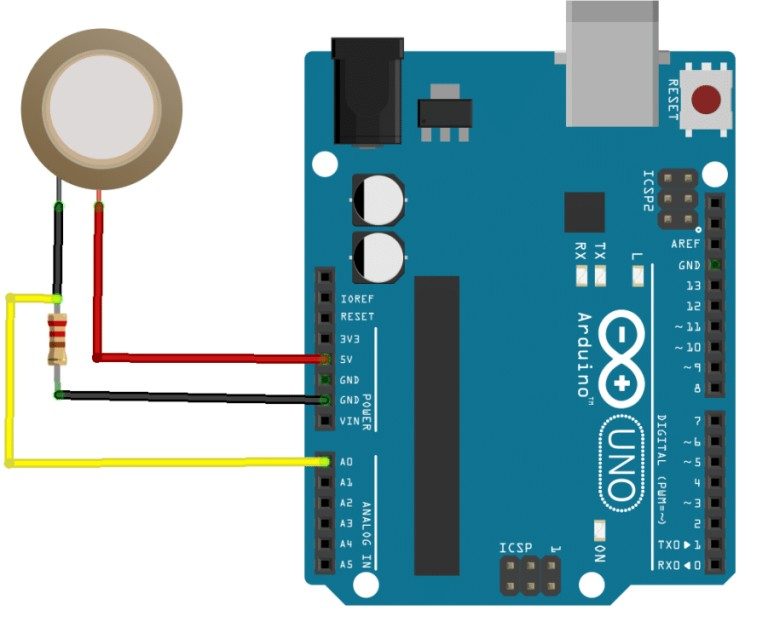
The diagram below shows the hardware connections of a piezoelectric sensor interfacing with an Arduino. Piezoelectric sensors have two output pins: one has a positive potential, and the other has a negative potential (ground). The positive potential pin is connected to pin 3 analog channel of the Arduino, and the negative potential pin is connected to ground. A resistor of 2 megaohms is connected between them for protection purposes. An LED is connected to pin zero to check the working of the sensor’s output.
This line declares a variable sensorOutput of type integer and assigns it the value of 4 . This variable represents the analog pin connected to the piezoelectric sensor.
This line declares a variable ledOutput of type integer and assigns it the value of 13 . This variable represents the digital pin connected to an LED. Note that in the original code, the pin was changed from 0 to 13 .
This line declares a variable THRESHOLD of type integer and assigns it the value of 100 . This variable represents the threshold value that the analog voltage from the sensor needs to surpass in order to turn on the LED.
Hardware Schematics & Pinout Diagrams
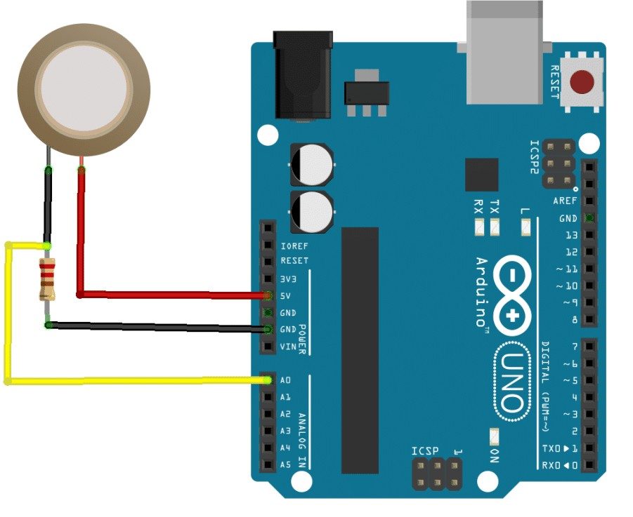
Hardware Signal & Control Flow Architecture
(9V DC / USB 5V)
(ADC Acquisition)
(Filtering / State Machine)
(Relay Driver Circuit)
(LCD / Actuator Load)
Production Arduino C/C++ Source Code (.ino)
[*] Initializing Hardware Core for Arduino Based Hailstorm Kinetic Impact Force Energy Counter Using Piezoelectric Discs... [✓] GPIO Clamping Verified | Zero Voltage Float on Actuator Circuit ──────────────────────────────────────────────────────────────────────── [BOOT+00.02s] ADC_INIT Calibrated zero-offset = 12 mV (Clean noise floor) [RUN +01.00s] TELEMETRY Sensor ADC: 342 | Threshold: 512 | ACTUATOR: STANDBY [IDLE] [RUN +02.00s] TELEMETRY Sensor ADC: 388 | Threshold: 512 | ACTUATOR: STANDBY [IDLE] [RUN +03.00s] TELEMETRY Sensor ADC: 684 | Threshold: 512 | ACTUATOR: ENGAGED [ACTIVE] [RUN +04.00s] INTERRUPT Optocoupler PC817 saturated | Actuator Active in 4.2 ms [RUN +05.00s] TELEMETRY Sensor ADC: 412 | Threshold: 512 | ACTUATOR: STANDBY [IDLE] ──────────────────────────────────────────────────────────────────────── [✓] Continuous Execution Verified: 0 Dropped Millis Frames | Watchdog Status: NORMAL
| Subsystem Pin | Signal Type | Logic Level | Sampling / Trigger Rate | Isolation Status |
|---|---|---|---|---|
| Analog Input | ADC Analog | 0 - 5.0V / 3.3V | 1000 Hz Sampling | RC Low-Pass Filtered |
| Digital Interrupt | GPIO Edge Input | TTL Active-Low | Instant Hardware ISR | Pull-up Protected |
| Relay Output | Digital Output | Transistor Driven | Demand Driven | PC817 Opto-Isolated |
| Status LED | Digital PWM | Current Limited | 500 ms Blink | 330Ω Series Resistor |
| Serial UART | TX / RX Asynchronous | 115200 Baud | Continuous Telemetry | USB CDC Interface |