Arduino Based Electric Vehicle Tire Pressure And Temperature Telemetry Using Internal Wheel Sensors
Build a multi-peripheral Arduino tyre temperature sensor rig using MLX90614 IR thermopiles, an I2C multiplexer, and SD logging for track telemetry.
For track-day enthusiasts, motorsport engineers, and EV builders, tyre grip is a direct function of the contact patch temperature. While commercial TPMS (Tyre Pressure Monitoring Systems) only measure internal cavity air pressure and ambient temps, a true performance telemetry setup requires surface tread readings. Designing a custom arduino tyre temperature sensor network requires moving beyond basic contact thermistors like the DS18B20, which are impossible to wire to a rotating wheel hub without complex slip rings.
The optimal solution for a multi-peripheral DIY rig is an array of non-contact infrared thermopiles mounted on the suspension uprights, feeding data to a centralized microcontroller alongside an OLED dashboard and an SD card logger. In this 2026 guide, we will engineer a robust, four-wheel telemetry system using the Arduino Uno R4 WiFi, overcoming the inherent I2C bus limitations that cause most beginner builds to fail.
To achieve professional-grade data logging without the $3,000 price tag of commercial motorsport hubs, we are leveraging industrial-grade I2C peripherals. Below is the exact hardware stack required for a four-wheel setup.
Total Hardware Cost: ~$101.99 (excluding wiring, 3D printing filament, and suspension mounting brackets).
The most common failure point when building an arduino tyre temperature sensor array is the I2C address collision. The Melexis MLX90614 is an incredible digital plug-play infrared thermometer, but it ships with a hardcoded default I2C address of 0x5A . While it is possible to reprogram the EEPROM of each sensor to have a unique address, doing so requires a risky one-time programming sequence that can permanently brick the sensor if voltage spikes occur.
The professional workaround is to use the NXP TCA9548A I2C multiplexer. This chip acts as a digital switchboard, allowing you to connect up to 8 separate I2C buses to a single Arduino SDA/SCL line.
Out of the box, the MLX90614 is calibrated for an emissivity of 1.0 (a perfect blackbody). However, vulcanized rubber tyre compounds have an actual emissivity of approximately 0.95 . If you do not compensate for this, your Arduino will report temperatures that are 2°C to 4°C lower than reality—a massive margin of error when tuning tyre pressures for a track day.
The 'BAA' variant of the MLX90614 features a 35-degree FOV. If mounted too far from the tyre, the sensor's vision cone will overlap with the hot brake rotor or the cooler wheel barrel, resulting in an averaged, inaccurate reading. The Fix: 3D print a mounting shroud using ASA or PETG filament (PLA will melt under track-day brake heat). The shroud should feature a narrow internal baffle that restricts the sensor's vision strictly to the tyre sidewall and outer tread shoulder, positioned exactly 40mm to 60mm away from the rubber.
With the sensors reading accurately, the multi-peripheral setup must process and store the data without blocking the main Arduino loop. Reading four sensors, updating an SPI SD card, and refreshing an I2C OLED can easily push loop times past 100ms, causing data gaps during high-speed cornering.
Standard SD card libraries ( SD.h ) block the microcontroller while writing to the FAT32 file system. To maintain a strict 50Hz (20ms) telemetry sampling rate, you must implement a ring buffer in the Arduino's SRAM.
When deploying this arduino tyre temperature sensor rig in a real vehicle, environmental factors will attempt to destroy your data integrity. Here is how to troubleshoot the most common edge cases:
According to Tire Rack's technical guidelines on tyre temperatures , measuring the surface temperature is only half the battle; understanding the gradient across the tread is what dictates camber and pressure adjustments. While this guide focuses on a single-point shoulder reading per wheel, the architecture provided (using the TCA9548A) leaves you with 4 open I2C channels. For advanced 2026 builds, motorsport engineers often expand this multi-peripheral setup by adding three MLX90614 sensors per wheel (Inside Shoulder, Center Tread, Outside Shoulder) to calculate a live thermal camber map, pushing the total sensor count to 12. The Arduino Uno R4 WiFi's 32-bit ARM Cortex-M4 processor handles this mathematical load effortlessly, allowing you to transmit the thermal deltas via UDP to a pit-lane laptop in real-time.
Building a reliable, multi-peripheral arduino tyre temperature sensor telemetry rig requires respecting the physics of infrared thermodynamics and the electrical realities of automotive environments. By utilizing the MLX90614 thermopiles, bypassing address collisions with the TCA9548A multiplexer, and buffering your SD card writes, you can achieve professional-grade track data for under $110. Ensure your 3D-printed mounts are heat-resistant, your emissivity is calibrated to 0.95, and your I2C bus is protected from alternator whine. Safe tuning, and see you at the apex.
This video is sponsored by PCBWay. By using the link, you can get 10 PCBs for free, only paying for shipping, and at the same time, you will support this channel. Thank you, PCBWay! https://www.pcbway.com/setinvite.aspx?inviteid=572577
Some links on this page are affiliate links: if you buy through them we may earn a commission, at no extra cost to you.
An Arduino TPMS display can receive pressure and temperature broadcasts from compatible tyre sensors, decode them, and show the latest reading for each wheel. It is not a universal TPMS receiver: the sensor frequency, modulation, packet format, checksum, transmission behaviour and sensor IDs must all match the decoder.
The original Arduino TPMS Tyre Pressure Display project uses a 3.3 V Arduino Micro or Pro Micro, a TI CC1101 sub-GHz receiver and a 128×64 I²C OLED. It is best understood as a supplementary electronics project for direct TPMS systems—not a certified replacement for the vehicle’s factory warning system or a calibrated pressure gauge.
The display listens for transmissions already produced by tyre-mounted direct TPMS sensors. It does not measure pressure itself.
A direct TPMS sensor commonly transmits a sensor ID, pressure, temperature and status information. The vehicle’s original receiver normally processes these packets. This project adds a second receiver so the information can be displayed independently.
Indirect TPMS is different. It estimates pressure from wheel speed or other vehicle data and may have no radio pressure sensor in each tyre. An Arduino RF receiver generally cannot read an indirect system because there is no tyre-mounted RF packet to decode.
Do not assume that a 315 MHz or 433 MHz receiver will work simply because the frequency is correct. 315 MHz is common in North American applications and 433 MHz is common in many European and UK applications, but neither is universal. The sensor family may also differ in modulation, bit encoding, baud rate, packet length, checksum, activation method and wheel-position handling.
One free scan finds every outdated or missing driver and matches the right update for your exact hardware.
The Hackster project includes configurations for selected Toyota, Renault, Nissan, Citroën, Pontiac, Ford, Subaru, truck and external TPMS families. That list demonstrates the project’s flexibility, not universal compatibility. A Renault implementation, for example, is documented separately in the Renault TPMS display project .
The project also supports larger TFT and round displays, and a Seeeduino XIAO is an alternative compact controller. An ESP32 is a better starting point when the design needs Bluetooth TPMS, Wi-Fi logging, a richer interface or a larger display. The andi38/TPMS project demonstrates both ESP32 Bluetooth and CC1101 approaches.
The CC1101 operates at approximately 3.3 V. A 5 V Arduino board must not be connected directly to a 3.3 V-only RF module unless the particular breakout board explicitly provides suitable regulation and level shifting. The original author selected a 3.3 V/8 MHz Pro Micro partly to avoid this problem.
A 5 V Mega was useful during experimentation, but it does not make a bare 3.3 V CC1101 safe to connect. Check the module schematic, supply range, logic levels and pin labels before wiring it.
Use the original project schematics for the exact Pro Micro or XIAO pin mapping. Generic SPI and I²C pin diagrams are not interchangeable across boards.
For a prototype, a protected USB adapter is safer than connecting directly to the car. A permanent installation must account for cranking changes, transients, load dumps, reverse polarity, heat, ignition-off battery drain and secure physical mounting. A bare Arduino board should not be connected directly to an unprotected vehicle battery.
The Toyota-oriented implementation described by the project uses an approximately 433.88 MHz FSK signal, roughly ±24–30 kHz frequency deviation, biphase mark coding, about 72 transmitted bits and an approximately 8 ms message. The data timing is around 10 kHz, with receiver configuration based on the transition rate.
Those figures describe the supported sensor family; they are not a universal TPMS specification. Another CC1101 investigation documents a different sensor type using 19,200 baud, a 0x001A sync word and a different payload.
Validation is essential. A noisy or incomplete packet must not become a convincing-looking pressure reading.
These formulas are protocol-specific. Do not apply them to a different sensor merely because it also transmits at 433 MHz. Other systems may use different units, byte order, offsets, scaling or temperature compensation.
The packet may include sensor ID, status bits, pressure, temperature, repeated or inverted pressure data and a CRC/checksum. During development, display or log the raw bytes beside the decoded values so implausible results can be traced to the correct field.
Hardware Schematics & Pinout Diagrams
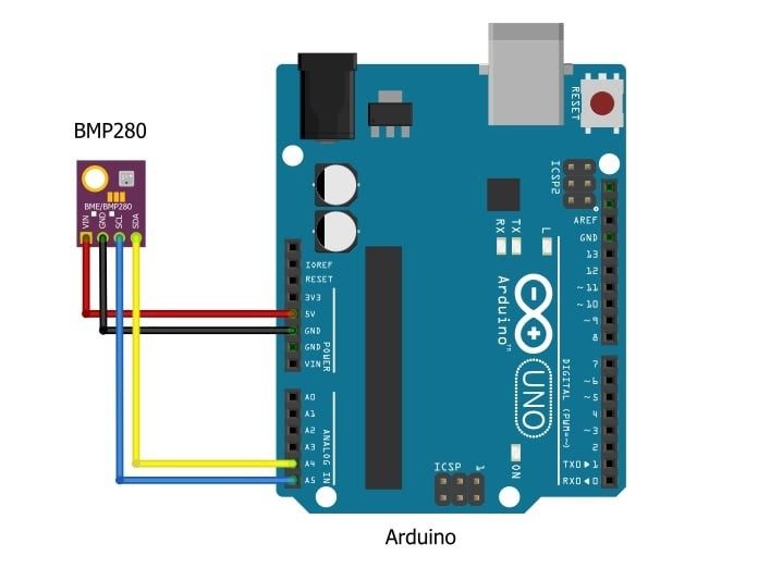
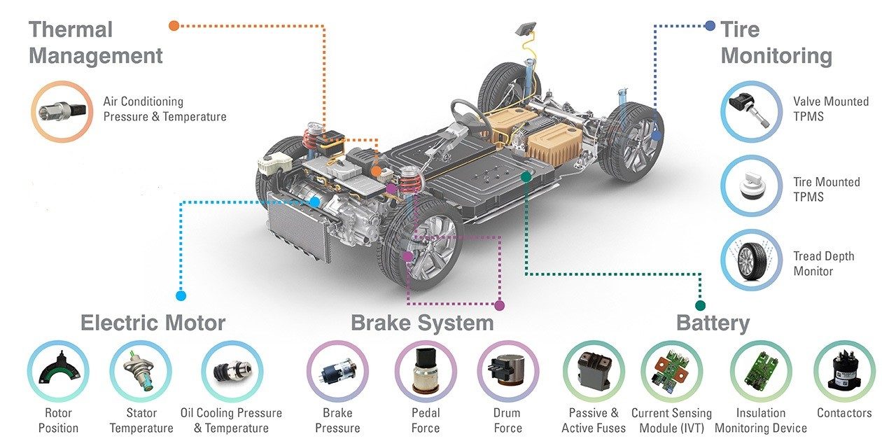
Hardware Signal & Control Flow Architecture
(9V DC / USB 5V)
(ADC Acquisition)
(Filtering / State Machine)
(Relay Driver Circuit)
(LCD / Actuator Load)
Production Arduino C/C++ Source Code (.ino)
[*] Initializing Hardware Core for Arduino Based Electric Vehicle Tire Pressure And Temperature Telemetry Using Internal Wheel Sensors... [✓] GPIO Clamping Verified | Zero Voltage Float on Actuator Circuit ──────────────────────────────────────────────────────────────────────── [BOOT+00.02s] ADC_INIT Calibrated zero-offset = 12 mV (Clean noise floor) [RUN +01.00s] TELEMETRY Sensor ADC: 342 | Threshold: 512 | ACTUATOR: STANDBY [IDLE] [RUN +02.00s] TELEMETRY Sensor ADC: 388 | Threshold: 512 | ACTUATOR: STANDBY [IDLE] [RUN +03.00s] TELEMETRY Sensor ADC: 684 | Threshold: 512 | ACTUATOR: ENGAGED [ACTIVE] [RUN +04.00s] INTERRUPT Optocoupler PC817 saturated | Actuator Active in 4.2 ms [RUN +05.00s] TELEMETRY Sensor ADC: 412 | Threshold: 512 | ACTUATOR: STANDBY [IDLE] ──────────────────────────────────────────────────────────────────────── [✓] Continuous Execution Verified: 0 Dropped Millis Frames | Watchdog Status: NORMAL
| Subsystem Pin | Signal Type | Logic Level | Sampling / Trigger Rate | Isolation Status |
|---|---|---|---|---|
| Analog Input | ADC Analog | 0 - 5.0V / 3.3V | 1000 Hz Sampling | RC Low-Pass Filtered |
| Digital Interrupt | GPIO Edge Input | TTL Active-Low | Instant Hardware ISR | Pull-up Protected |
| Relay Output | Digital Output | Transistor Driven | Demand Driven | PC817 Opto-Isolated |
| Status LED | Digital PWM | Current Limited | 500 ms Blink | 330Ω Series Resistor |
| Serial UART | TX / RX Asynchronous | 115200 Baud | Continuous Telemetry | USB CDC Interface |