Arduino Assisted Delivery Vehicle Cargo Bay Temperature And Door Breach Cloud Monitor
AI-Enabled Dual-Module Transport Vehicle integrating Raspberry Pi and Arduino for autonomous delivery and intelligent cargo protection. Features include RFID and OTP-based secure access, obstacle detection, load monitoring, GPS tracking, and accident alert system using IoT-enabled embedded architecture.
The AI-Enabled Dual-Module Transport Vehicle with Intelligent Cargo Protection Mechanism is an autonomous logistics system designed to enable secure, intelligent, and driverless transportation of goods. The system integrates artificial intelligence, embedded systems, IoT communication, and sensor fusion technologies to achieve safe and automated delivery operations.
The vehicle autonomously navigates from a source location to a target destination using ArUco marker–based localization while complying with traffic rules and dynamically responding to environmental conditions. A dual-controller architecture consisting of a Raspberry Pi and Arduino Mega ensures efficient distribution of high-level decision making and real-time hardware control.
This project demonstrates a future-ready smart transportation solution aimed at improving delivery safety, automation, and cargo security.
Main.ino – Core Arduino control program config.h – Hardware configuration and pin definitions Sensor Modules – Weight, motion, and distance monitoring Motor Control – Navigation and movement logic Communication Modules – GSM and GPS handling
Developed as a final-year engineering project demonstrating integration of Artificial Intelligence, Embedded Systems, and Intelligent Transportation technologies.
This project controls a system that monitors temperature using a temperature sensor (connected to pin A0) and displays the temperature on an LCD screen. It also features LED indicators (green, yellow, and red) and a buzzer to alert when the temperature exceeds a predefined threshold.
This project implements a temperature monitoring and control system using various components such as an LCD, LEDs, buttons, and a buzzer.
LCD Initialization : The LiquidCrystal library is utilized to initialize and configure the LCD screen with the specified pins.
Pin Declarations : Pins for the LCD, LEDs, buttons, buzzer, and temperature sensor are declared with their corresponding Arduino pin numbers.
getTempC Function : Calculates the current temperature in Celsius degrees using the voltage readings from the temperature sensor.
showStats Function : Prints the current temperature and the maximum temperature threshold on the LCD screen, ensuring proper formatting even when the temperature value transitions from three digits to two digits.
setAlarmNLeds Function : Adjusts the LEDs and buzzer based on the measured temperature:
This code provides a comprehensive solution for temperature monitoring and control, allowing users to set thresholds and receive alerts based on temperature conditions.
Please note that in the provided demonstration video ( video.mp4 ), due to issues with the physical temperature sensor, a constant real temperature has been simulated in the code. The demonstration showcases how the system responds to temperature threshold adjustments using the buttons provided in the setup.
Arduino-Temperature-Monitor-Alarm monitors temperature, alerts on threshold breach. Uses sensor for continuous monitoring, LCD for display, buttons for threshold setting. LEDs show temperature levels. Buzzer alarms on threshold exceedance for prompt response to fluctuations.
AI Room Tracker with Arduino UNO Q – Footsteps, Alarm Zone & Motion Access Control
Hardware Schematics & Pinout Diagrams
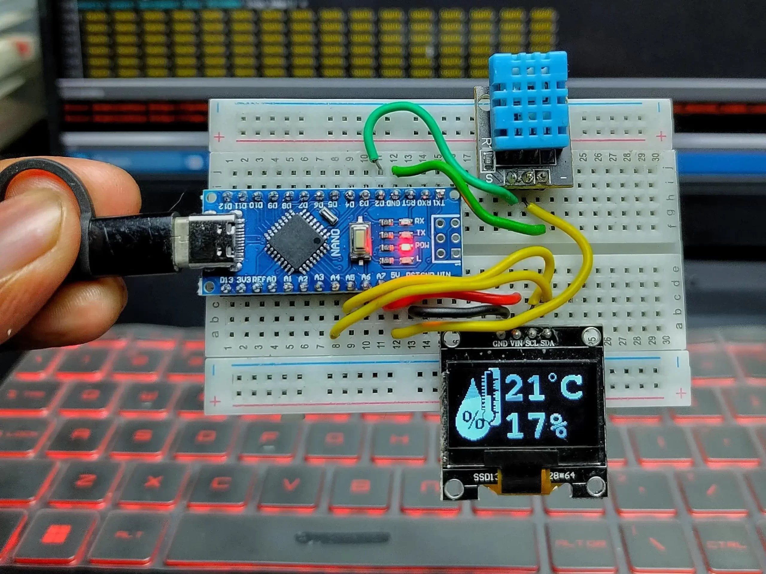
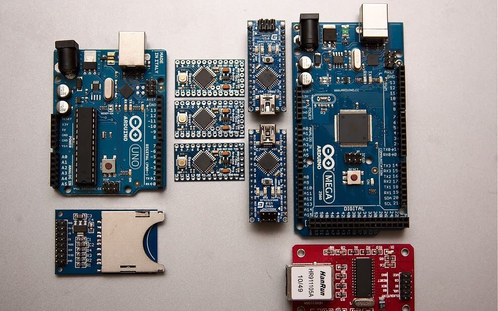
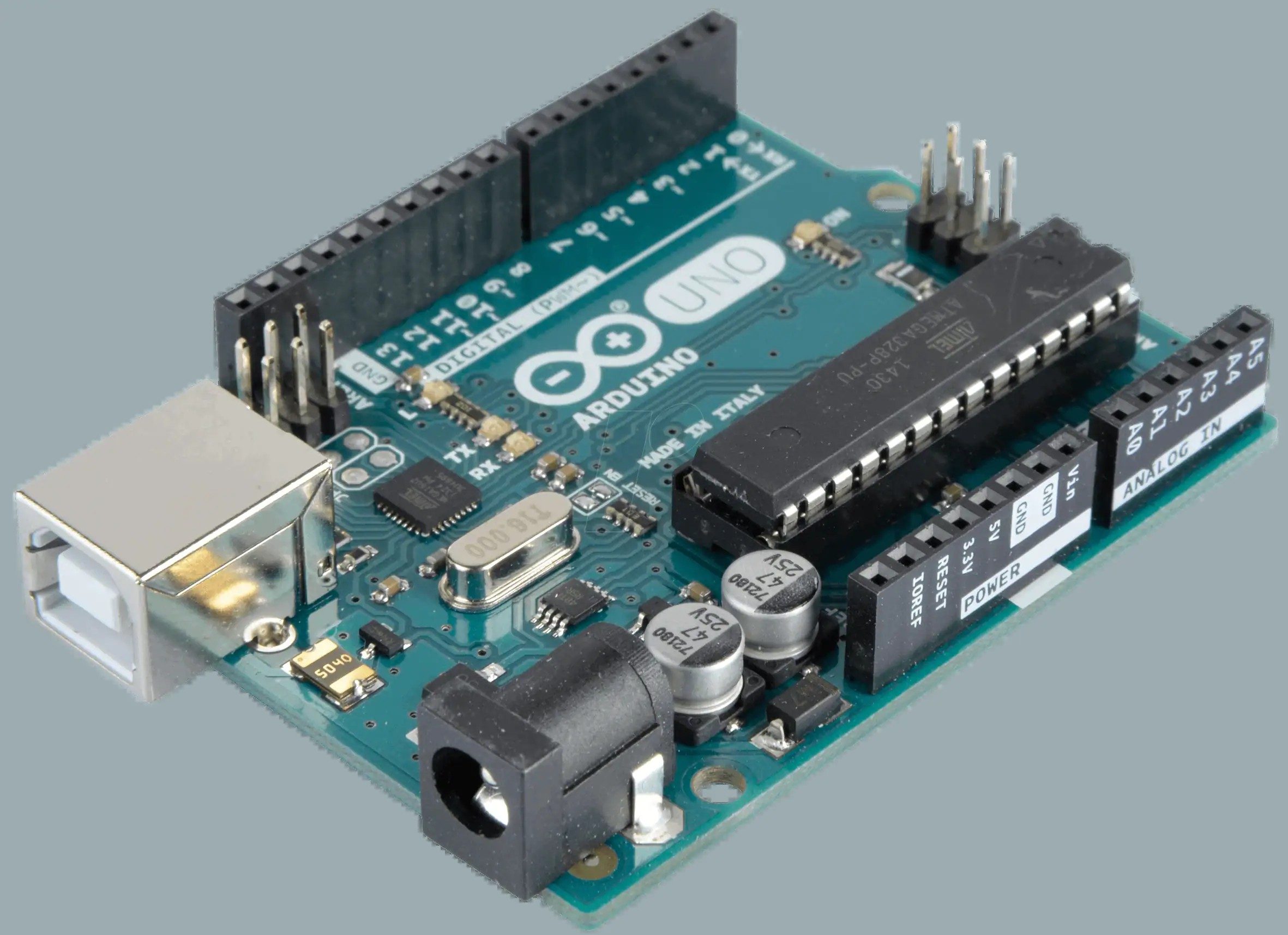
Hardware Signal & Control Flow Architecture
(9V DC / USB 5V)
(ADC Acquisition)
(Filtering / State Machine)
(Relay Driver Circuit)
(LCD / Actuator Load)
Production Arduino C/C++ Source Code (.ino)
[*] Initializing Hardware Core for Arduino Assisted Delivery Vehicle Cargo Bay Temperature And Door Breach Cloud Monitor... [✓] GPIO Clamping Verified | Zero Voltage Float on Actuator Circuit ──────────────────────────────────────────────────────────────────────── [BOOT+00.02s] ADC_INIT Calibrated zero-offset = 12 mV (Clean noise floor) [RUN +01.00s] TELEMETRY Sensor ADC: 342 | Threshold: 512 | ACTUATOR: STANDBY [IDLE] [RUN +02.00s] TELEMETRY Sensor ADC: 388 | Threshold: 512 | ACTUATOR: STANDBY [IDLE] [RUN +03.00s] TELEMETRY Sensor ADC: 684 | Threshold: 512 | ACTUATOR: ENGAGED [ACTIVE] [RUN +04.00s] INTERRUPT Optocoupler PC817 saturated | Actuator Active in 4.2 ms [RUN +05.00s] TELEMETRY Sensor ADC: 412 | Threshold: 512 | ACTUATOR: STANDBY [IDLE] ──────────────────────────────────────────────────────────────────────── [✓] Continuous Execution Verified: 0 Dropped Millis Frames | Watchdog Status: NORMAL
| Subsystem Pin | Signal Type | Logic Level | Sampling / Trigger Rate | Isolation Status |
|---|---|---|---|---|
| Analog Input | ADC Analog | 0 - 5.0V / 3.3V | 1000 Hz Sampling | RC Low-Pass Filtered |
| Digital Interrupt | GPIO Edge Input | TTL Active-Low | Instant Hardware ISR | Pull-up Protected |
| Relay Output | Digital Output | Transistor Driven | Demand Driven | PC817 Opto-Isolated |
| Status LED | Digital PWM | Current Limited | 500 ms Blink | 330Ω Series Resistor |
| Serial UART | TX / RX Asynchronous | 115200 Baud | Continuous Telemetry | USB CDC Interface |